
AMBA APB · Module 8
Why Wait States Exist
The engineering reasons a subordinate cannot always answer in one cycle — slow SRAM, clock-domain synchroniser stages, gated or divided peripheral clocks, shared-resource arbitration, and multi-step internal operations — and why the single-cycle-response assumption is the idealisation wait states exist to break.
The textbook APB transfer completes in two cycles — setup, then access — as if every target answers the instant it is addressed. That is a convenient lie. Real peripherals have internal latency: a multi-cycle SRAM, a synchronizer chain across a clock boundary, a clock that runs slower than PCLK, an arbiter busy with another port, a register whose value must first be computed. The single-cycle-response assumption is an idealization; wait states exist because real subordinates need time, and PREADY=0 is APB's way of letting a slow target hold the bus until it can answer. This chapter establishes the why; later chapters in Module 8 handle the how.
1. Problem statement
The problem is reconciling a synchronous, fixed-cadence bus with subordinates that have variable, multi-cycle internal latency — without corrupting data and without redesigning the bus per peripheral.
APB is a simple, low-bandwidth control bus. Its transfer model is deliberately rigid: the manager presents an address and control in the setup phase, asserts PENABLE for the access phase, and expects the access to resolve. But the manager's idea of "resolve" — the access completes on the next PCLK edge — only holds if the subordinate can genuinely produce read data (or accept write data) in that one cycle. Many cannot:
- The data is not there yet. A pipelined SRAM, a register file with a read latency, or a value that crosses a clock domain is simply not available on the first access edge. If the manager completes anyway, it captures whatever happens to be on the bus — stale, partial, or metastable.
- The target is not free yet. A peripheral behind an arbiter, or one whose clock is gated off, cannot service the request right now; it must wait for its turn or for its clock to run.
So the manager needs a way to ask "are you done?" each cycle and believe the answer. That is exactly what PREADY is: a per-cycle backpressure bit the subordinate drives low to say "not yet — hold the bus," and high to say "now — complete." The existence of wait states is not a feature anyone wanted; it is the unavoidable consequence of putting slow things on a fixed-cadence bus, and PREADY is the minimum mechanism that makes that safe. Chapter 8.2 — slow-peripheral behaviour walks through what the bus actually looks like cycle by cycle once a slow peripheral starts stretching accesses; this chapter establishes why the latency is there in the first place.
2. Why previous knowledge is insufficient
Module 3 — the PREADY handshake named PREADY as the completion-and-backpressure control: high completes, low waits. Module 5 — access-phase timing drilled the per-cycle cadence — that the manager samples PREADY on every PCLK edge while PENABLE is high and decides, on that edge, whether to complete or hold. Both are correct and necessary, and both stop exactly where this chapter begins:
- Module 3 told you the contract; it did not tell you who needs it. Knowing that
PREADY=0inserts a wait answers "what does the bit do." It does not answer "why would a subordinate ever drive it low?" — and a designer who cannot name the latency sources will either forget to insert waits (and capture garbage) or insert them everywhere (and waste cycles). The reason lives inside the peripheral, not in the handshake. - Module 5 told you the cadence; it treated the subordinate as a black box that simply chooses to be ready or not. The cadence view never asks why the subordinate is not ready on edge one. That "why" — SRAM read latency, synchronizer depth, a divided clock, arbitration, a multi-step op — is the entire content of this chapter, and it is what lets you predict how many waits a given peripheral will insert and when.
- Neither covered clock-domain reality. Both prior chapters implicitly assume the subordinate is on
PCLK. A huge fraction of real wait states come from the subordinate being on a different, slower, or asynchronous clock — a fact invisible at the handshake level but central to why waits exist at all.
So the model to add is causal: not "the subordinate drives PREADY low," but "the subordinate has an internal source with real latency, and PREADY=0 is how that latency is exported onto the bus." That causal model is what lets you reason about a waveform, size a peripheral's worst-case latency, and decide whether a wait is legitimate or a bug.
3. Mental model
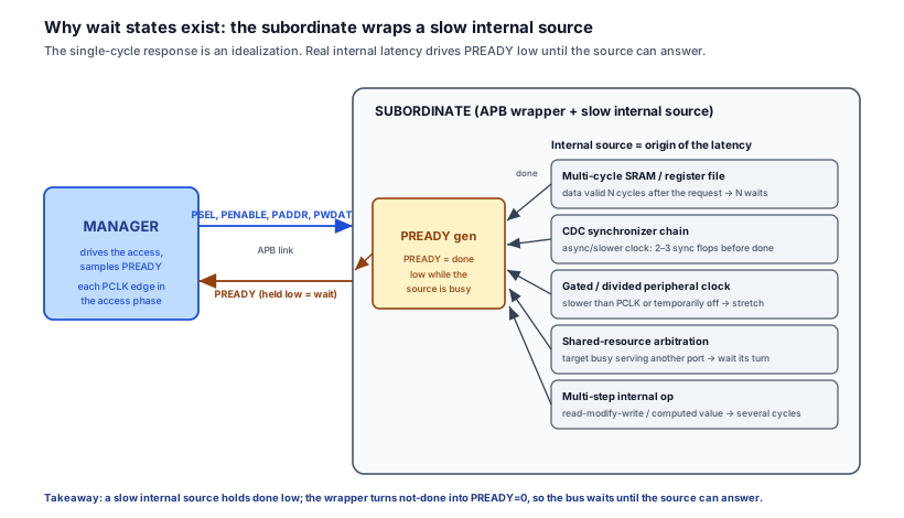
The model: the subordinate is not an oracle that answers instantly — it is a thin APB wrapper around a slow internal source, and PREADY is just that source's "done" signal exported onto the bus. Whenever the internal source needs N cycles, the wrapper holds PREADY low for N cycles. Wait states are not a bus feature; they are internal latency made visible.
Picture the wrapper as a translator standing at the bus. The manager asks "is the answer ready?" every PCLK edge. The translator turns and looks at the internal source — the SRAM, the synchronizer, the arbiter — and relays its done flag as PREADY. If the source says "still working," the translator says PREADY=0 and the manager holds. When the source finally says "done, here's the data," the translator says PREADY=1 and the access completes. The number of wait states is dictated entirely by the source's latency, not by anything on the bus.
Five concrete sources fill in why the internal done is late:
- Multi-cycle memory. An SRAM, a pipelined register file, or flash returns data one or more cycles after the request. The wrapper holds
PREADYlow until the data is on its read port. - Clock-domain-crossing synchronizers. If the peripheral's registers live in a different (often slower or asynchronous) clock domain, the request and its response must cross through a multi-flop synchronizer. Those
2–3(or more) synchronizing flops are the wait cycles — there is no faster-than-physics way to safely cross a clock boundary. - Gated or divided clocks. If the peripheral clock is
PCLK/4, the peripheral only advances one of every fourPCLKcycles, so an access naturally stretches. If the clock is gated off for power, the access waits until it is re-enabled. - Shared-resource arbitration. When the addressed target is also serving another port (a DMA, a second bus), the request waits in arbitration until it is granted. The wait length depends on the other traffic, so it is variable.
- Multi-step internal operations. A read-modify-write, a value that must be computed, or a status register that aggregates several sources cannot be presented in one cycle; the FSM takes several cycles, holding
PREADYlow until the result is final.
The unifying idea: every one of these is latency inside the subordinate, and PREADY=0 is the single, uniform way APB exports any of them onto a bus that otherwise assumes everything is instant.
4. Real SoC implementation
In a real SoC, the APB subordinate is the wrapper from Figure 1 made concrete: an FSM that issues a request to the internal source and holds PREADY low until the source signals done. The sketch below is a peripheral whose read data crosses from an asynchronous, slower domain through a synchronizer — the single most common cause of wait states on real control buses — and a parallel comment shows the SRAM-latency case, which is structurally identical.
// APB subordinate wrapping a slow internal source.
// Read data lives in an asynchronous/slower domain and must cross a 2-flop
// synchronizer, so it is NOT valid on the first access edge. PREADY exports
// that latency onto the bus: low until the synchronized "done" arrives.

  typedef enum logic [1:0] {IDLE, REQ, WAIT, DONE} state_t;
  state_t state;

  // Request pulse into the peripheral's domain (CDC-safe handshake omitted for
  // brevity; in real RTL this would be a toggle/ack pair, not a bare pulse).
  logic req_pulse;

  // "done" comes back from the source's domain through a synchronizer.
  // These sync flops ARE the wait cycles — you cannot cross a clock boundary
  // safely in zero time, so PREADY must stay low while they fill.
  logic done_meta, done_sync;
  always_ff @(posedge pclk or negedge presetn) begin
    if (!presetn) begin done_meta <= 1'b0; done_sync <= 1'b0; end
    else          begin done_meta <= src_done; done_sync <= done_meta; end
  end

  always_ff @(posedge pclk or negedge presetn) begin
    if (!presetn) begin
      state    <= IDLE;
      pready   <= 1'b1;          // default ready when idle: never hang the bus
      req_pulse<= 1'b0;
    end else begin
      req_pulse <= 1'b0;
      unique case (state)
        IDLE: if (psel && !penable) begin     // setup phase: request seen
                 state     <= REQ;
                 pready    <= 1'b0;            // we already know we'll be slow
               end
        REQ:  begin
                 req_pulse <= 1'b1;            // kick the slow source
                 state     <= WAIT;
                 pready    <= 1'b0;            // hold: data is in transit
               end
        // Hold PREADY low for the WHOLE crossing. For a multi-cycle SRAM this
        // is identical: replace done_sync with sram_rvalid (asserted N cycles
        // after the read request) and the structure is the same.
        WAIT: if (done_sync) begin
                 prdata <= src_rdata;          // capture only now — data is valid
                 pready <= 1'b1;               // complete on this access edge
                 state  <= DONE;
               end
        DONE: begin                            // single completion cycle
                 pready <= 1'b1;
                 state  <= IDLE;
               end
      endcase
    end
  end
Two facts make this representative of real silicon. First, the wait count is not a constant the designer picks — it is dictated by the source. Here it is the synchronizer depth plus crossing handshake; for an SRAM it is the read latency; for an arbitrated target it is variable (you do not know how long the arbiter will make you wait, so the FSM must be data-driven, not a fixed counter). Second, the default-ready rule still applies: an idle or unselected subordinate drives PREADY high so it never stalls the bus — the slowness is asserted only once a request that targets this slave is in flight. (How that held-low PREADY then extends the access edge by edge is chapter 8.4 — transfer extension; here the point is simply why done_sync is late.)
5. Engineering tradeoffs
Different latency sources cost different things and imply different wait counts. Choosing where to put a peripheral — and how to wrap it — is a real architectural decision, because the wait states are paid on every access for the life of the chip.
| Latency source | Typical waits | Variable or fixed? | What it costs | How to mitigate |
|---|---|---|---|---|
| Multi-cycle SRAM / register file | 1–3 | Fixed (known read latency) | Throughput on every read | Add a small read cache; pipeline if the bus allows; accept it (control reads are sparse) |
| CDC synchronizer chain | 2–4+ | Fixed (sync depth) but only on crossing | Latency on every crossing access | Put hot registers in the PCLK domain; use a single crossing per access, not per-bit; batch accesses |
| Gated / divided peripheral clock | clock-ratio dependent | Fixed by the divide ratio; large if gated off | Access stretches by the ratio; long stall if clock must be re-enabled | Keep frequently-accessed regs on PCLK; wake the clock early; avoid divided clocks on the access path |
| Shared-resource arbitration | 0 to many | Variable (depends on other traffic) | Unbounded worst case; jitter | Add a fast path / dedicated port for the bus; bound arbitration latency; size the worst case in the timing budget |
| Multi-step internal op (RMW, computed reg) | 2–N | Fixed by the op | Latency on those specific accesses | Pre-compute where possible; split into a "start" write and a "poll" read so the bus is not held |
The throughline: the cheapest wait is the one you avoid by placing the data on the fast clock. Synchronizers, divided clocks, and arbitration each add latency that is paid forever, so the highest-leverage decision is architectural — what lives on PCLK versus across a boundary — not the RTL of the wait itself. And the most dangerous source is arbitration, because its latency is variable and potentially unbounded: a fixed wait-state counter will be wrong, so an arbitrated peripheral must drive PREADY from the actual grant, never from a hard-coded count.
6. Common RTL mistakes
7. Debugging scenario
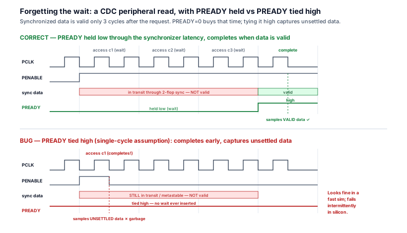
A peripheral that reads correctly in a quick RTL sim but returns intermittently wrong values on the bench is the signature failure of this chapter: a slow internal source that was treated as single-cycle, so the required wait state was never inserted.
- Observed symptom: firmware reads a status/data register from a peripheral and occasionally — not always — gets a wrong or stale value; re-reading usually returns the correct value. It passed every directed RTL simulation and only fails on silicon (or in gate-level with real clocks), and it gets worse as the bus clock speeds up or the peripheral clock slows down.
- Waveform clue: in a gate-level or multi-clock waveform (Figure 2),
PREADYis tied high for this peripheral, so the access completes on the very first access edge — but the peripheral's read data is still propagating through its2-flop synchronizer at that instant and has not settled. The manager samplesPRDATAwhile the synchronizer output is mid-transit (sometimes the new value, sometimes the old, sometimes metastable), which is exactly why the failure is intermittent. - Root cause: the peripheral's registers live in a slower/asynchronous clock domain, but the APB wrapper was written assuming single-cycle response and hard-tied
PREADY=1. No wait states are ever inserted, so the manager completes before the synchronized data is valid. The design omitted the wait the clock crossing physically requires. - Correct RTL: drive
PREADYfrom the synchronizeddone, holding it low through the crossing —WAIT: if (done_sync) begin prdata <= src_rdata; pready <= 1'b1; end else pready <= 1'b0;— and capturePRDATAonly on the cycledone_syncasserts. Never tiePREADYhigh for a peripheral whose source has latency; let the source'sdonegate completion. - Verification assertion: assert that the access never completes before the source has signalled done — i.e. completion implies the data was valid:
Pair it with a coverage point that the peripheral does exercise the multi-wait path, so a suite that only ever hits the (impossible) zero-wait case is flagged as having a hole.Azvya Education Pvt. Ltd.VLSI MentorSnippet
// An access may only complete (PREADY high in access) once the source is done. assert property (@(posedge pclk) disable iff (!presetn) (psel && penable && pready) |-> done_sync) else $error("APB access completed before internal source produced valid data"); - Debug habit: when a peripheral read is intermittently wrong but logically correct, do not re-read the register decode — ask "what clock is this peripheral's data actually on, and how many cycles does it take to be valid?" Then check whether
PREADYis tied high or counts to fewer waits than the source needs. Intermittent-on-silicon, clean-in-RTL almost always means a missing wait across a latency boundary.
8. Verification perspective
Wait-state existence bugs — a missing or wrong-length wait on a latency source — are easy to miss because a naive directed test on an idealized model never reproduces them. Verifying this topic means attacking the causality (data valid before complete) and the latency profile (right number of waits) at the right level.
- Assert ready-before-valid causality. The single most important property is that an access never completes before the internal source's data is genuinely valid:
(psel && penable && pready) |-> source_done. This catches the tied-high and short-counter bugs directly, and it is the assertion that fails when someone treats a slow source as single-cycle. Bind it at the wrapper, where bothPREADYand the source'sdoneare visible. - Cover the latency profile, not just "a wait happened." Functional coverage must bin how many wait states each peripheral inserts — zero (only legal for a genuinely single-cycle source), one, several, and the worst-case — and, for arbitrated targets, cover the contended path where another port forces extra waits. A suite that only ever sees a fixed wait count never proves the variable-latency path works.
- Pick the level that exposes the real failure. Many of these bugs are clock-domain bugs, so they are invisible in a single-clock zero-delay RTL run that pretends the peripheral is on
PCLK. Use a multi-clock / asynchronous testbench (or gate-level with real clock relationships) so the synchronizer latency and the divided/gated clock actually exist; randomize the clock-ratio and the async phase so the wait count varies run to run. RTL with a faithful clock model catches the causality bug; only a true multi-clock or gate-level run reproduces the metastable-capture flavour. - Drive the source's latency from the stimulus. Model the SRAM/CDC/arbiter latency as a randomized, configurable delay in the slave model so the environment naturally produces
0..Nwaits and back-to-back accesses with different latencies, rather than a single hard-coded number that hides the corner.
The point: this topic is verified by proving why the wait must exist — data-valid-before-complete and a correct, possibly variable, latency profile — and by running it at a level where the clock domains and arbitration are real, not idealized away.
9. Interview discussion
"Why would an APB subordinate ever insert a wait state?" is a deceptively deep question — a weak answer says "to add delay," a strong answer enumerates the physical causes and ties them back to the protocol.
Frame the answer as internal latency exported onto a fixed-cadence bus: APB assumes a one-cycle response, but real targets have latency the bus must accommodate, and PREADY=0 is the uniform mechanism. Then enumerate the sources with their character — multi-cycle memory (SRAM/regfile read latency, fixed), clock-domain crossing (synchronizer flops, fixed but only on the crossing; the highest-value point because it shows you think about clocks), gated or divided clocks (the peripheral simply runs slower than PCLK), shared-resource arbitration (the killer point: latency is variable and potentially unbounded, so you cannot use a fixed counter), and multi-step ops (read-modify-write, computed registers). Deliver the depth: the wait count is dictated by the source, not chosen by the designer, so an arbitrated peripheral must drive PREADY from the actual grant; and completing before the source is done captures wrong data, not just an early result — the wait protects correctness, not just timing. Closing with "the cheapest wait is the one you avoid by keeping hot registers on PCLK; the most dangerous is arbitration, because its latency is unbounded" signals you have actually budgeted a real SoC's bus latency.
10. Practice
- Name the source. For each of these, state how many wait states (fixed or variable) you expect and why: a register on
PCLK; a status register synchronized from a32 kHzalways-on domain; a data register behind a 2-cycle SRAM; a peripheral behind an arbiter shared with a DMA. - Fixed vs variable. Explain why a hard-coded wait-state counter is correct for an SRAM but a bug for an arbitrated target, and what you drive
PREADYfrom in each case. - Trace the latency. On the Figure 1 model, draw the path from
PADDRtoPRDATAfor a CDC peripheral and mark which flops are the wait cycles. - Predict the silicon failure. A peripheral on a divided clock has
PREADYtied high. Describe the symptom you'd see on the bench and why it is intermittent rather than constant. - Place the data. Given a peripheral with three hot registers across an async boundary, propose two architectural changes that reduce its per-access wait count, and state the cost of each.
11. Q&A
12. Key takeaways
- Wait states are internal latency made visible. The single-cycle response is an idealization; a real subordinate is a thin APB wrapper around a slow source, and
PREADY=0is the uniform way that source's latency is exported onto the bus. - There are five recurring sources: multi-cycle memory (SRAM/regfile), clock-domain-crossing synchronizers, gated or divided clocks, shared-resource arbitration, and multi-step internal operations (read-modify-write, computed registers).
- The wait count is dictated by the source, not chosen by the designer. Fixed-latency sources (SRAM, sync depth) can use a counter; variable ones (arbitration) must drive
PREADYfrom the actualdone/grant, never a hard-coded count. - Completing before the source is done captures wrong data, not just an early result — stale, partial, or metastable. The wait protects correctness, not merely timing.
- The most common silicon bug here is a missing wait across a clock boundary: a CDC peripheral treated as single-cycle,
PREADYtied high, returning intermittently wrong data that passes single-clock RTL sim and only fails on real clocks. - The cheapest wait is the one you avoid architecturally by keeping hot registers on
PCLK; verify the topic with a data-valid-before-complete assertion and a latency-profile coverage model, run at a multi-clock or gate-level level where the crossings and arbitration are real.
Continue learning
Related tutorials
- Related topic
Slow-Peripheral Behaviour
How a real slow peripheral manifests its internal latency on the bus — its busy-to-done state machine driving PREADY, fixed versus variable latency profiles, and how one logical register read becomes a multi-cycle transaction the manager must reason about.
- Related topic
Access-Phase Timing Anatomy
The access phase cycle by cycle — PENABLE held high, PREADY sampled on every rising edge to decide wait-or-complete, and the single completion edge where PRDATA, the write commit, and PSLVERR are captured.
- Related topic
Transfer-Extension Mechanics
The cycle-by-cycle mechanics of how PREADY=0 holds the access phase — what the manager freezes (PADDR, PWDATA, PWRITE, PSEL, PENABLE) and why, what it re-samples each held edge, and the exact completion condition. An extended transfer is one transfer stretched, not many.
- Related topic
Multi-Cycle Transfers
How PREADY held low stretches a transfer across multiple cycles — one and multi-wait timing, the signals held stable through the wait, and why a wait stretches access without restarting setup.
Standards & specifications
- Governing standard
- Arm AMBA APB Protocol Specification (IHI 0024)(opens Arm in a new tab)
Defines the APB setup/access phases and the PREADY and PSLVERR signalling. Peripheral register layout and verification approach are outside its scope.
This page also covers RTL structure, verification approach and debugging technique. Those are engineering practice built on the standard, not requirements the standard itself imposes.
Where this fits
Part of the AMBA APB curriculum.