
UART tutorials, labs & MCQs.
A UART curriculum built for RTL design, verification and FPGA engineers — asynchronous timing first principles (drift, per-frame recovery, the real tolerance budget) before the start bit, then frame semantics, baud generation, receiver sampling and oversampling strategies, RX and TX RTL architecture, error and break behaviour, FIFOs and flow control, a complete UART IP, CDC / reset / implementation concerns, SoC register and interrupt integration, verification strategy, assertions and coverage, a UVM environment, waveform-driven debugging, and integrated engineering case studies.
Tutorials
Learn UART from beginner to advanced through structured tutorials.
Labs
Practice UART using progressively challenging hands-on labs.
MCQs
No MCQ papers for UART yet.
What UART is
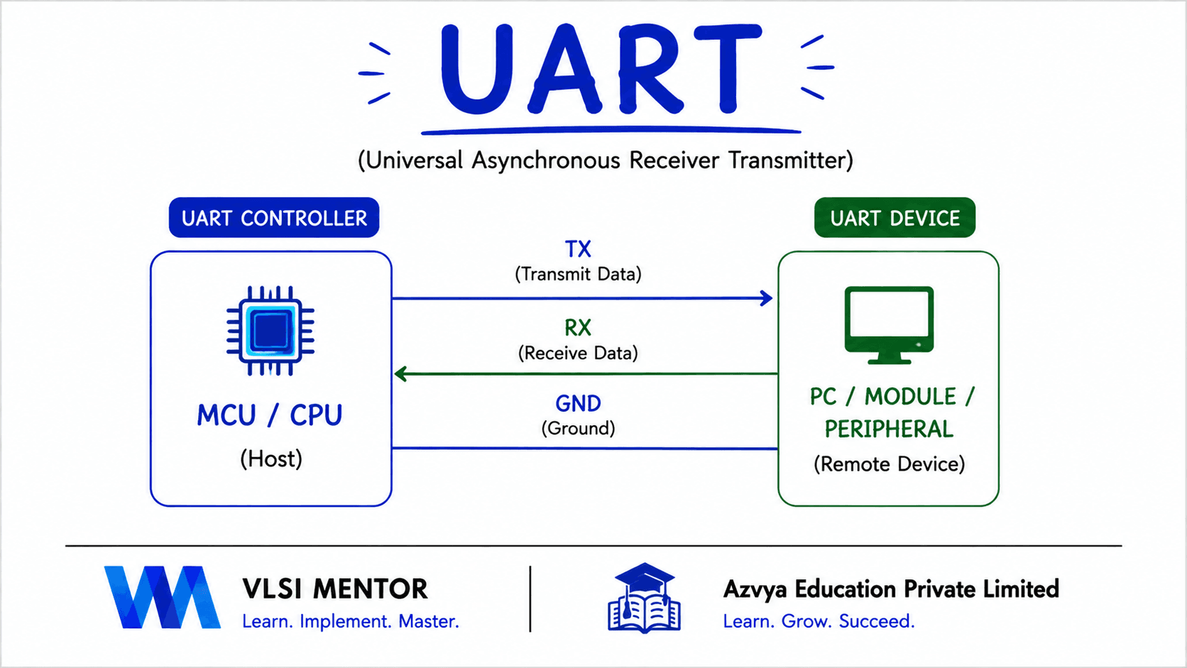
A UART is the logic that lets two digital systems exchange data over very few wires when no clock travels alongside it. Inside a device it is an ordinary synchronous block: it accepts a parallel byte on the system clock and returns one. On the line it produces and observes timed activity on a timebase derived from a rate both ends were configured with in advance, and a matching block at the far end reconstructs the byte from that timing evidence alone. The acronym — universal asynchronous receiver/transmitter — names the two independent halves and the defining property. Around that conversion, production UART IP adds the parts an SoC needs: a baud generator, buffering so software is not obliged to service every character, error and status reporting, and a register interface. It is the interface almost every chip still boots and logs on.
Why it exists
Carrying a byte between devices in parallel form costs eight signal wires plus whatever qualifies them, and for a console log or a handful of configuration registers that cost is absurd. Sending a clock alongside serialised data solves the timing problem and costs another pin and a tighter timing relationship. UART takes the remaining option — send nothing but the data — which makes it the cheapest link that still works between two independently clocked systems. That is why it survives: as the boot console a board is brought up on, the debug port a firmware engineer reaches for first, and the low-rate link between a controller and a module that does not justify anything larger. For a hardware engineer it is also the smallest complete interface worth building: a transmitter, a receiver, a timebase, error handling and a bus attachment, all small enough to hold in your head at once.
The part engineers get wrong
The habit to build early is separating what UART framing actually requires from how UART IPs conventionally implement it. Oversampling, a particular oversampling factor, majority voting, a specific vote depth, FIFOs, flow control and interrupts are all engineering choices with real justifications — none of them is part of the definition, and presenting one as a requirement is how a claim becomes wrong the first time you meet a different implementation. The second thing worth holding is the asymmetry between the two halves. The transmitter creates the timing, so its job is sequencing and it is not where the difficulty lives. The receiver must recover timing it was never given, from a rate that only approximately matches, which is where nearly every real UART failure originates. The third is that a configuration mismatch does not break a link — it corrupts it, sometimes undetectably, which is why UART debugging is dominated by evidence from the wire rather than from status registers.
Before you start
- Digital design — synchronous logic, counters, shift registers and state machines
- Basic RTL fluency in Verilog or SystemVerilog
- Helpful but not required: any prior exposure to a register map or an embedded console
What you will be able to do
- Explain what a UART converts between, and what information the receiver must reconstruct
- Separate UART framing from the electrical layer that carries it, and from the IP built around it
- Derive a baud divider and state the timing budget a given frame and receiver can actually tolerate
- Design a receiver's start detection and sampling strategy, and justify the choices as implementation rather than protocol
- Build transmitter and receiver RTL, a baud generator as a clock enable, and the FIFOs and flow control around them
- Plan and execute UART verification — reference model, assertions, coverage and deliberate error injection
- Read a UART capture and identify baud mismatch, bit-order, parity, framing and overrun failures by signature
The learning path
- Mental model and timingWhat a UART is, why asynchronous serial works, and where the timing margin comes from
- Framing and rateThe frame contract, configuration space, baud generation and the tolerance budget
- ReceptionStart detection, sampling and oversampling strategy, then receiver RTL architecture
- Transmission and timebaseTransmitter RTL, the ready/busy contract, and the baud generator as a clock enable
- Errors, buffering and flow controlFraming, parity, overrun and break; FIFOs, thresholds and RTS/CTS
- A complete IPTop-level assembly, CDC and reset, synthesis, and the register, interrupt and DMA interface
- VerificationVerification planning, reference models, assertions, coverage and error injection, then a UVM environment
- Debug and bring-upFailure signatures on the wire, FPGA capture, and integrated engineering case studies
Core concepts
New to UART? Work through the curriculum in order — each lesson assumes the one before it, and the sequence is what turns the roadmap above into working knowledge.
Already working with it? Use the core-concept links above to jump straight to the topic you need; each one opens the lesson that covers it in most depth.