AMBA AHB · Module 13
Multiple Slaves
How many slaves attach to an AHB interconnect and are selected — each shares the broadcast address/control bus, receives a unique HSEL from the decoder, and adds its read data, HREADYOUT, and HRESP to a response mux that returns the active slave's outputs to the master. Adding a slave grows the decoder, mux, and address map; hierarchy bounds the growth.
Chapter 13.1 framed the multi-master side; this chapter covers the multiple-slaves side — how many slaves (memories, peripherals, blocks) attach to the interconnect and are selected. The mechanism builds directly on the decoder module (Module 11): each slave shares the broadcast address/control bus (HADDR, HWRITE, HTRANS, …), receives a unique HSEL from the decoder (which asserts exactly one per access), and contributes its outputs (HRDATA, HREADYOUT, HRESP) to a response multiplexer that returns the active slave's response to the master. So attaching a slave means three wirings: tap the broadcast bus, get an HSEL, join the response mux. Adding a slave grows the decoder (one more comparison + HSEL), the response mux (one more input), and the address map (one more region) — but not the shared bus (it's just fanned out). At large slave counts, hierarchical decode (slaves grouped into blocks behind sub-decoders) bounds the growth. This chapter details how slaves attach, get selected, and scale.
1. What Is It?
Multiple slaves means many bus targets (memories, peripherals, blocks) attach to the interconnect, and the decoder selects the addressed one. Attaching a slave involves:
- Broadcast bus — the slave taps the shared address/control bus (HADDR, HWRITE, HTRANS, HSIZE, HBURST), which is broadcast to all slaves.
- Unique HSEL — the decoder gives the slave a dedicated select line, asserted when its address region is accessed (chapter 11.2).
- Response mux — the slave's outputs (HRDATA, HREADYOUT, HRESP) feed a multiplexer that returns the active slave's response to the master.
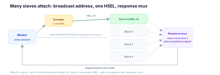
So multiple slaves is the fan-out side of the interconnect: the address/control fans out to all slaves (broadcast), the decoder picks one (HSEL), and the responses fan in through a mux (selected back to the master). This is the decoder/HSEL machinery of Module 11 applied at the scale of many slaves. Attaching a new slave slots into this structure: it joins the broadcast (input side) and the mux (output side), and gets a decoder HSEL and an address-map region. So multiple slaves is the structured attachment of many targets to a shared bus, selected by the decoder and returned through a response mux. This is the slave-side complement to the master-side arbitration of 13.1.
2. Why Does It Exist?
The multiple-slaves structure — broadcast bus, per-slave HSEL, response mux — exists because it's the efficient way to connect many targets to a shared bus: broadcasting the address avoids per-slave address routing, the decoder centralizes selection, and the mux centralizes the response return.
The broadcast avoids per-slave address routing: the master drives one address/control bus. Rather than routing a separate address to each slave (expensive, and the master would need to know which slave), the interconnect broadcasts the one address bus to all slaves — they all see it. This is cheap (a fan-out, no per-slave address logic) and keeps the master simple (it drives one address, oblivious to which slave). So broadcasting exists because it's the efficient way to deliver the address to many slaves. So the input side is a broadcast.
The decoder centralizes selection: with all slaves seeing the address, something must pick the one that should respond — the decoder (chapter 11.1). It's centralized (one decoder, not per-slave self-decode) so the address map is single-source-of-truth and slaves are relocatable (chapter 11.1). It outputs one HSEL per slave, one-hot. So the decoder exists to centrally select the addressed slave from the broadcast. So selection is centralized. So multiple slaves attach to a broadcast bus with central decode.
The response mux centralizes the return: each slave drives its own response outputs (HRDATA, HREADYOUT, HRESP), but the master needs one set of response signals — from the active slave. So a multiplexer (controlled by the decode) selects the active slave's outputs and returns them to the master. This centralizes the response return (one mux, not each slave driving the master's inputs directly — which would be contention). So the mux exists to combine the many slaves' responses into the one the master sees. So the output side is a mux. So the multiple-slaves structure — broadcast (input), decode (select), mux (output) — exists because it's the efficient, scalable way to attach many slaves: broadcast the address once, select centrally, return through a mux. And the reason adding a slave grows only the decoder, mux, and map (not the bus) is that the bus is broadcast (fan-out, free to extend) while selection and response-return are per-slave (so they grow). So the structure scales gracefully — and hierarchical decode (grouping slaves into blocks, chapter 11.7) exists to keep each decoder/mux small at large counts, bounding the growth. So multiple slaves exist with this structure because it's the efficient, scalable attachment of many targets to a shared bus.
3. Mental Model
Model multiple slaves as a radio broadcast with addressed listeners and a single call-in line — the host (master) broadcasts one signal that every station (slave) receives, but only the station whose call-sign is announced (HSEL) responds; and when a station replies, it goes through one shared call-in line (the response mux) back to the host, so the host hears only the responding station, not all of them at once.
A radio host (the master) broadcasts one signal (the address/control) that every station (slave) in range receives — the host doesn't send a separate signal to each station; it's one broadcast, heard by all. But the host announces a call-sign (the decoder asserts one HSEL): only the station whose call-sign is announced is supposed to respond; the others, hearing the broadcast but not their call-sign, stay quiet. When the addressed station replies, it doesn't shout over the air alongside everyone — it goes through one shared call-in line (the response mux), which connects only the responding station to the host. So the host broadcasts to all but hears back from one — the call-sign selects who responds, and the single call-in line carries that one response back. Adding a new station means it joins the broadcast audience (free — it just tunes in), gets assigned a call-sign (the decoder), and gets a slot on the call-in line (the mux) — but the broadcast itself doesn't change.
This captures multiple slaves: the broadcast signal = the address/control bus (broadcast to all); every station receiving it = all slaves seeing HADDR; announcing a call-sign = the decoder asserting one HSEL; only that station responding = only the selected slave responds; the single call-in line = the response mux; the host hearing one response = the master getting the active slave's response. Broadcast to all, select one by call-sign, hear back through one line — adding a station is just tuning in + a call-sign + a call-in slot.
Watch the response mux select the addressed slave's output:
Response mux returns the active slave's data
4 cyclesThe model's lesson: broadcast to all, select one by call-sign, hear back through one line. In the waveform, the response mux returns whichever slave is addressed — the master sees the active slave's response, following the decode.
4. Real Hardware Perspective
In hardware, multiple slaves means the address/control fans out to all slaves, the decoder produces per-slave HSEL lines, and the response mux (read-data + HREADY + HRESP) selects the active slave — with hierarchical decode and registered muxing managing timing at scale.
The broadcast fan-out is cheap on the input side: HADDR, HWRITE, HTRANS, HSIZE, HBURST (and HWDATA for writes) are fanned out to all slaves — wires driven to every slave's inputs. This is a fan-out load (which, at large slave counts, may need buffering for timing), but no per-slave logic. So in hardware, the input side scales as fan-out (with buffering as needed). So adding a slave just adds it to the fan-out.
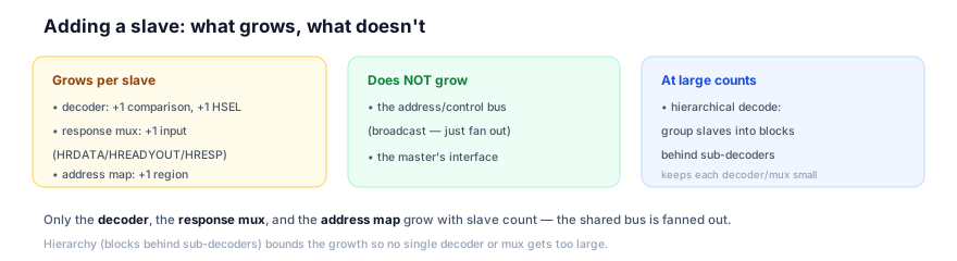
The response mux is the output side: the read-data mux selects the active slave's HRDATA; similarly HREADY and HRESP are selected from the active slave (HREADY aggregation is detailed in chapter 13.7). This mux grows with slave count (more inputs → a wider/deeper mux), and at large counts becomes a timing concern (a wide mux is slow) — so it may be registered (pipelined) or hierarchical (per-block muxes feeding a top mux). So in hardware, the response mux scales with slaves and is managed for timing. So adding a slave widens the mux.
The hierarchical decode manages scale (chapter 11.7): rather than one flat decoder selecting among all slaves (a large decoder) and one wide mux, slaves are grouped into blocks — a top decoder selects a block, a sub-decoder selects the slave within it, and muxes are per block feeding a top mux. So each decoder/mux stays small (few inputs), and the structure matches physical grouping (e.g. a peripheral block behind a bridge). So at large slave counts, hierarchy keeps the logic manageable. So in hardware, multiple slaves attach via broadcast fan-out (input), per-slave HSEL from the decoder, and a response mux (output) — with hierarchical decode and registered/hierarchical muxing keeping timing in check at scale. The decoder, mux, and address map grow with slave count; the bus does not. So the hardware scales gracefully, bounded by hierarchy.
5. System Architecture Perspective
At the system level, the multiple-slaves structure is what lets an SoC's address space be populated with many memories and peripherals cleanly — and it composes with the multi-master side (13.1) to form the full interconnect, where the matrix's per-slave structure is key.
The populating the address space view: an SoC has many targets — multiple memories (ROM, RAM, external), many peripherals (UART, timers, GPIO, …), and special blocks — all living in the address space (chapter 11.4). The multiple-slaves structure is how they all attach: each gets an address-map region, an HSEL, and a response-mux slot. So the structure is the mechanism by which the address map is realized in connected hardware — every region in the map corresponds to an attached slave. So at the system level, multiple slaves is how the address space becomes a populated, accessible set of targets. Adding a peripheral to the SoC = adding a slave (region + HSEL + mux slot). So the structure scales with the SoC's target count.
The composition with multiple masters view: 13.1 (masters) and 13.2 (slaves) compose into the full interconnect. On a shared bus, there's one decoder + one response mux (for the one active master). In a bus matrix, the slave-side structure is replicated per master path — or, more precisely, each slave port has its own arbiter (multiple masters can target it) and the routing connects any master to any slave. So the matrix is the cross-product of the master side and slave side: M masters × S slaves, with per-slave arbitration and per-master routing. So the multiple-slaves structure (decode + mux) is a building block of the matrix. So at the system level, multiple slaves composes with multiple masters to form the matrix — understanding both is prerequisite to the matrix (chapter 13.3). So the slave side is half the interconnect.
The scalability discipline view: as the SoC grows (more memories, more peripherals), the slave count grows, and the structure must scale without blowing up decoder/mux size or timing. The discipline is hierarchy (chapter 11.7): group slaves into blocks (a peripheral block, a memory subsystem), each behind a sub-decoder and sub-mux, so the top-level decode/mux stays small. This also matches physical organization (slaves grouped by function/speed, e.g. peripherals on a slower bus behind a bridge). So the slave side scales by hierarchy, keeping each decode/mux small and matching the physical layout. So at the system level, the multiple-slaves structure populates the SoC's address space with many targets, composes with the multi-master side to form the interconnect/matrix, and scales by hierarchy to keep the logic and timing manageable as the SoC grows. It's the slave-side foundation of the interconnect — and the matrix (the next chapters) builds on it by giving each slave its own arbitration so multiple masters can be served. So multiple slaves is the scalable attachment mechanism that, combined with multiple masters, makes the full fabric.
6. Engineering Tradeoffs
Multiple slaves embody the broadcast-select-mux attachment design.
- Broadcast bus vs per-slave routing. Broadcasting the address to all slaves is cheap (fan-out, simple master) at the cost of fan-out load (buffering at scale). Per-slave address routing would be expensive and complex. Broadcast is standard.
- Central decode + mux vs per-slave self-decode. A central decoder + response mux gives a single-source address map, relocatable slaves, and clean response return, at the cost of central logic that grows with slaves. Per-slave self-decode scatters the map. Central is standard (chapter 11.1).
- Flat vs hierarchical decode/mux. Flat (one decoder, one wide mux for all slaves) is simple at small counts but large/slow at scale; hierarchical (blocks behind sub-decoders/sub-muxes) keeps each small and matches physical grouping. Use hierarchy as slave count grows.
- Registered vs combinational mux. A combinational response mux is lowest-latency but slow when wide (large slave count); a registered/pipelined mux eases timing at a latency cost. Wide muxes are often registered or hierarchical.
The throughline: many slaves attach to the interconnect by sharing the broadcast address/control bus, each receiving a unique HSEL from the central decoder (one-hot per access) and feeding its outputs (HRDATA, HREADYOUT, HRESP) to a response mux that returns the active slave's response to the master. Adding a slave grows the decoder (one comparison + HSEL), the response mux (one input), and the address map (one region) — but not the shared bus (broadcast, fanned out). Hierarchical decode/mux (blocks behind sub-decoders) bounds the growth and matches physical grouping. This is the slave-side foundation that composes with the multi-master side to form the matrix.
7. Industry Example
Trace attaching slaves in an SoC.
An SoC has ROM, SRAM, external memory, and a peripheral block (UART, timer, GPIO behind a bridge).
- The address map defines the slaves. Each target has a region: ROM at
0x0000_0000, SRAM at0x2000_0000, the peripheral block at0x4000_0000, external memory at0x8000_0000(chapter 11.4). The map is the spec. - The decoder gives each an HSEL. The top decoder compares HADDR's upper bits and asserts ROM's, SRAM's, the bridge's, or external memory's HSEL. The peripheral block's sub-decoder (in the bridge) further selects UART/timer/GPIO (chapter 11.7). So each slave (and sub-slave) has its select.
- Slaves share the broadcast bus. HADDR/HWRITE/HTRANS are broadcast to all slaves; each sees the access but responds only when its HSEL is high.
- The response mux returns the active slave. When the CPU reads SRAM, the response mux returns SRAM's HRDATA/HREADY/HRESP; when it accesses a peripheral, the mux (and the bridge's) returns that peripheral's response. The master always sees the active slave's response.
- Adding a new peripheral (e.g. SPI). To add an SPI controller: add its region to the address map (
0x4000_3000, within the peripheral block), add a sub-decode entry (so the bridge asserts SPI's PSEL), and add SPI's outputs to the peripheral-block response mux. The top-level decoder/mux (which see the block) don't change — the addition is contained in the peripheral block (hierarchy). So the SPI is reachable and its responses return, with a localized change. - Hierarchy bounds growth. Because peripherals are grouped behind the bridge, adding the SPI touches only the block's sub-decoder/sub-mux, not the top-level fabric — keeping the top decode/mux small regardless of how many peripherals exist.
The example shows multiple slaves in action: the map defines them, the decoder selects them via HSEL, they share the broadcast bus, and the response mux returns the active one — with hierarchy (the peripheral block) bounding the growth so adding a slave is a localized, consistent change to map + sub-decoder + sub-mux. This is how SoCs attach their many targets.
8. Common Mistakes
9. Interview Insight
Multiple slaves is a structural interview topic — the broadcast/HSEL/mux mechanism and the what-scales question are the signals.
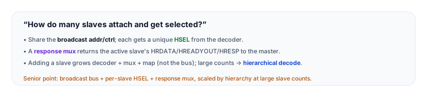
The answer that lands gives the mechanism and the scaling: "Many slaves attach to the interconnect by sharing one broadcast address and control bus — the master drives one HADDR, fanned out to all slaves, so they all see every access. The decoder then asserts exactly one slave's HSEL based on the address, so only the addressed slave responds. Each slave drives its own read data, HREADYOUT, and HRESP, and these feed a response multiplexer controlled by the decode, which returns the active slave's outputs to the master. So it's broadcast on the input side, decode to select, and mux on the output side. When you add a slave, three things grow: the decoder (one more comparison and HSEL), the response mux (one more input), and the address map (one more region) — but the shared bus itself doesn't grow; it's just fanned out to the new slave. And the three must stay consistent — a region in the map, the matching HSEL from the decoder, and the slave's input on the mux. At large slave counts, you use hierarchical decoding — grouping slaves into blocks behind sub-decoders and sub-muxes — to keep each decoder and mux small and match the physical organization, like peripherals grouped behind a bridge." The broadcast/HSEL/mux mechanism, the what-scales answer, and the consistency/hierarchy points are the senior signals.
10. Practice Challenge
Reason from multiple slaves.
- The structure. Describe how a slave attaches: broadcast bus, HSEL, response mux.
- What scales. State what grows when you add a slave (and what doesn't).
- Read the waveform. From Figure 2, explain how the response mux follows the decode to return the active slave's data.
- Consistency. Explain the three places attaching a slave touches and why they must agree.
- Hierarchy. Explain how hierarchical decode/mux keeps the logic small at large slave counts.
11. Key Takeaways
- Many slaves attach by sharing the broadcast address/control bus, each receiving a unique HSEL from the central decoder (one-hot per access), and feeding their outputs (HRDATA, HREADYOUT, HRESP) to a response mux that returns the active slave's response to the master.
- Input = broadcast, select = decode, output = mux — the address fans out to all, the decoder picks one, the mux returns the active slave's response.
- Adding a slave grows the decoder, the response mux, and the address map — but not the shared bus (broadcast, fanned out) or the master's interface.
- The three must stay consistent — map region ↔ decoder HSEL ↔ mux input, all for the same slave — or the slave is unreachable, its response is lost, or there's contention. Flows generate decoder + mux from one map description.
- Hierarchical decode/mux (slaves grouped into blocks behind sub-decoders/sub-muxes) keeps each decoder/mux small at large counts and matches physical grouping; slave addition becomes localized.
- It's the slave-side foundation of the interconnect — composing with the multi-master side (and per-slave arbitration) to form the bus matrix.
12. What Comes Next
You now understand how many slaves attach and are selected. The next chapter introduces the structure that combines the master and slave sides for concurrency:
- The Bus Matrix Concept (next) — the multi-layer bus matrix and its parallelism, the heart of the interconnect module.
- Parallel Slave Access, Decoder + Arbiter Combination, Interconnect Routing, HREADY Aggregation, Bus Matrix Performance — the matrix mechanics and performance.
To revisit the decode and HSEL this builds on, see Address Decoding and HSEL Generation; for the multi-master side, see Multiple Masters.