AMBA AHB · Module 3
HADDR & HWRITE
The AHB address bus and direction control in detail — HADDR's width, byte addressing, and alignment to the transfer size, and HWRITE's read/write encoding.
With the global signals (HCLK, HRESETn) established, we begin the address-phase signals at full detail. This chapter covers the two most fundamental: HADDR, the address bus that says where, and HWRITE, the single bit that says which direction. You met both at the role level in chapter 2.3; here we pin down HADDR's width and byte-addressing, the all-important alignment rule that ties it to the transfer size, and HWRITE's exact encoding. These are the signals the decoder reads to route every access and that the subordinate reads to know whether to expect or produce data — so getting their detail right is foundational to everything that follows.
1. What Is It?
HADDR is the address bus: the manager drives it in the address phase to specify where the access goes. Its key properties:
- It is commonly 32 bits wide (some systems use wider, up to 64), giving the address space the bus can reach.
- It is a byte address — each distinct HADDR value names one byte of the address space.
- It is driven by the manager in the address phase and read by the decoder to select the subordinate.
- It must be aligned to the transfer size (the subject of HSIZE): a word access on a 4-byte boundary, a halfword on a 2-byte boundary, a byte anywhere.
HWRITE is the direction control — a single bit, also driven in the address phase:
- HWRITE = 1 means a write: the manager will drive the data (on HWDATA) to the subordinate.
- HWRITE = 0 means a read: the selected subordinate will drive the data (on HRDATA) back to the manager.
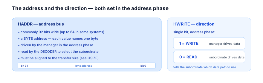
Together these two signals answer "where and which way": HADDR routes the access to a subordinate and HWRITE tells that subordinate whether to accept incoming data or produce outgoing data. They are the most basic pair of the address phase, and almost every other signal refines or qualifies the access these two define.
2. Why Does It Exist?
These two signals exist because every memory-mapped access fundamentally requires two pieces of information before anything else: what location and which direction.
HADDR exists to name the location. AHB is a memory-mapped bus: subordinates occupy ranges of a shared address space, and an access is directed by its address. HADDR is how the manager expresses "I want to access this location," and it is the input to the decoder that turns that location into a subordinate selection. Without an address bus there would be no way to target a specific subordinate or a specific location within it — the whole memory-mapped model rests on HADDR. Its width sets how large an address space the bus can reach (32 bits → a 4 GB byte-addressable space), and its byte granularity means it can name individual bytes, which matters for sub-word accesses.
HWRITE exists to name the direction. A bus must carry data both ways — managers both store to and load from subordinates — and the subordinate needs to know which is happening before the data phase, so it can prepare to either capture incoming write data or drive outgoing read data. HWRITE carries that one bit of intent in the address phase, alongside the address, so by the time the data phase arrives, the subordinate already knows whether to listen or to speak. Putting direction in the address phase (not the data phase) is essential: the subordinate must be set up for the correct direction before any data moves.
The alignment rule exists for a hardware reason we will detail shortly, but conceptually: larger accesses occupy naturally-aligned positions in memory, and requiring HADDR to respect that keeps the byte-lane mapping between the address and the data bus simple and unambiguous. Alignment is the rule that makes HADDR and the transfer size (HSIZE) consistent.
So HADDR and HWRITE exist because the two irreducible questions of any access are "where?" and "which way?", and these signals carry exactly those, in the address phase, so the access is fully directed before its data moves.
3. Mental Model
Model HADDR and HWRITE as the address and the direction on a shipping label.
Every parcel needs a destination address (HADDR) and a marking of whether it is an outbound shipment or a return/pickup (HWRITE). The sorting facility (the decoder) reads the address to route the parcel to the right destination, completely independent of whether it is outbound or inbound. The destination, reading the direction marking, knows whether to expect a delivery (a write — incoming data to capture) or to prepare a shipment back (a read — outgoing data to provide). The label is filled out and read before any goods move — exactly the address phase preceding the data phase.
Watch a read followed by a write, the two HWRITE values in action:
Read (HWRITE=0) then write (HWRITE=1)
4 cyclesThe model's takeaway: HADDR and HWRITE are set per transfer in its address phase, and HWRITE decides who drives data in the following data phase. Notice in the waveform that read data and write data appear on different buses (HRDATA vs HWDATA) — the separate read/write data paths from chapter 2.1 — and HWRITE is what selects which one carries this transfer's data.
4. Real Hardware Perspective
In hardware, HADDR and HWRITE are straightforward manager outputs, but two details matter: the alignment rule's physical reason, and the address-phase hold obligation.
Alignment and byte lanes. The data bus is divided into byte lanes, and the address determines which lanes a sub-word access uses. For the mapping between an address and its byte lanes to be simple and unambiguous, an access of a given size must sit on a naturally-aligned boundary: a word (4 bytes) on a multiple of 4, a halfword on a multiple of 2, a byte anywhere.
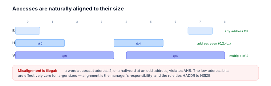
Because of alignment, the low address bits are effectively fixed for larger sizes (the low 2 bits are zero for a word, the lowest bit is zero for a halfword), and the hardware can rely on that to wire byte lanes simply. AHB does not support misaligned accesses; the manager must align HADDR to HSIZE, and doing otherwise is a protocol violation that real subordinates are not built to handle.
The address-phase hold rule applies to HADDR and HWRITE. As established in chapter 2.3, the manager must hold its address-phase signals stable until the access completes. So if a subordinate inserts wait states (HREADY low), HADDR and HWRITE must remain unchanged for the whole extended access — the subordinate is relying on them being valid throughout. Changing HADDR or HWRITE mid-access corrupts the transfer. In hardware, the manager registers these outputs and only advances them when the current access completes (HREADY high on a rising edge).
A third practical detail: because HADDR is read combinationally by the decoder within the address-phase cycle, the path from the manager's HADDR through the decoder to the subordinate select is a real timing path, and on large address maps it can be timing-critical. This is why address maps and decoders are designed with care — HADDR's propagation through decode must fit inside its cycle so the subordinate is selected in time for the data phase.
5. System Architecture Perspective
At the system level, HADDR is the signal that realizes the address map, and HWRITE interacts with the system's access-control and data-path structure.
HADDR and the address map. The chip's address map — the assignment of address ranges to subordinates — is implemented by the decoder reading HADDR. So HADDR is where the architectural address map becomes live routing: each range an architect assigns becomes a set of HADDR values the decoder maps to one subordinate. The width of HADDR bounds the total addressable space, and how the address bits are partitioned (which high bits select the subordinate, which low bits index within it) is the physical form of the memory map. When you see a memory map document, the decoder turning HADDR into selects is its hardware embodiment, every access.
HWRITE and access direction system-wide. HWRITE's direction bit also feeds system-level features. A memory-protection or access-control unit may use HWRITE (alongside HPROT and the address) to decide whether a write to a particular region is permitted — for instance, write-protecting a code region. So HWRITE is not only "which data bus" but a piece of the access's intent that protection logic can act on. And because HWRITE selects between the separate read and write data paths, it is integral to the data-path architecture from chapter 2.1: the separate HWDATA and HRDATA buses exist, and HWRITE picks which one is active for this transfer.
Alignment and the wider system. The alignment rule has a system consequence: software and compilers must produce aligned accesses for word and halfword data, and data structures are laid out with alignment in mind. A processor's load/store unit generates aligned HADDR/HSIZE combinations; a DMA engine's address generation respects alignment. So the alignment rule at the signal level propagates up into how software and hardware lay out and access memory — a small protocol rule with broad system reach.
Together, HADDR and HWRITE connect the signal level to two major system structures: the memory map (via HADDR and the decoder) and the access-control/data-path architecture (via HWRITE). They are simple signals with system-wide significance.
6. Engineering Tradeoffs
The design decisions around HADDR and HWRITE are few but real.
- Address width: reach vs cost. A wider HADDR reaches a larger address space but costs more wires across the whole bus and interconnect, and a larger decoder. 32 bits (4 GB) is the common sweet spot for the embedded systems AHB targets; going wider is only justified when the address space genuinely demands it. The trade is addressable range versus wiring and decode cost.
- Byte addressing vs word addressing. A byte address (each value names a byte) supports sub-word accesses and matches how processors view memory, at the cost of needing the alignment rule to keep byte-lane mapping clean. A word-only address would be simpler but could not express byte/halfword accesses. AHB chooses byte addressing for flexibility and pays for it with the alignment discipline.
- Mandatory alignment: simplicity vs flexibility. Requiring aligned accesses keeps the hardware simple (clean byte-lane mapping, fixed low address bits) but forbids misaligned accesses that some software might find convenient. AHB chooses hardware simplicity; software and compilers must produce aligned accesses, and misaligned access is simply unsupported. The trade is hardware simplicity versus software flexibility, resolved firmly toward hardware.
- Direction in the address phase: setup vs late binding. Putting HWRITE in the address phase means the subordinate knows the direction early and can prepare, but it also means the direction is committed before the data phase — you cannot "decide later." This early commitment is exactly what enables the subordinate's preparation and the clean separate-data-bus design, so it is the right trade for a pipelined bus.
The through-line: HADDR and HWRITE are optimized for clean, simple hardware — a sensible address width, byte addressing with mandatory alignment, and direction committed early in the address phase. Each choice favours predictable, cheap hardware over maximal flexibility, consistent with AHB's whole design philosophy.
7. Industry Example
Trace HADDR and HWRITE through a few real accesses on a microcontroller.
- A word instruction fetch (read). The processor fetches a 32-bit instruction from flash. It drives HADDR with the instruction's address — necessarily a multiple of 4, because it is a word access — and HWRITE = 0 (a read). The decoder routes the address to the flash controller; flash, seeing HWRITE = 0, prepares to drive the instruction back on HRDATA in the data phase. Alignment is automatic here because instruction addresses are word-aligned by construction.
- A byte write to a peripheral register (write). Firmware writes a single byte to a control register. It drives HADDR with the register's byte address (any alignment is fine for a byte access) and HWRITE = 1 (a write). The decoder routes to the peripheral (or its bridge); the peripheral, seeing HWRITE = 1, prepares to capture the byte from HWDATA in the data phase. The byte address's low bits select which byte lane carries the data.
- A halfword DMA access (alignment matters). A DMA engine moves 16-bit samples. Each access drives HADDR with an even address (halfword alignment) and the appropriate direction on HWRITE. If the DMA were misconfigured to start at an odd address for halfword transfers, it would violate alignment — an insidious bug, because the hardware would not cleanly reject it.
- The hold rule in action. Suppose the flash fetch above hits a wait state (flash is slow). The processor holds HADDR and HWRITE stable for every wait cycle — the flash controller is relying on the address and direction remaining valid while it works. Only when HREADY goes high and the fetch completes does the processor advance HADDR/HWRITE to the next access.
Every access on the bus, in every chip, sets these two signals first: where, and which way. The decoder routes on HADDR, the subordinate prepares its data direction on HWRITE, and the alignment rule silently constrains every HADDR the manager is allowed to drive. They are the bedrock of the address phase.
8. Common Mistakes
9. Interview Insight
HADDR and HWRITE questions usually probe the alignment rule and the direction encoding — the two places candidates slip.
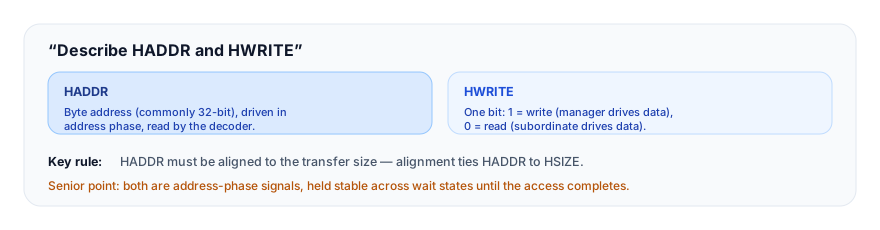
The answer that lands gives the encodings precisely and volunteers alignment: "HADDR is the byte address — commonly 32 bits — driven by the manager in the address phase and read by the decoder to select the subordinate. It must be aligned to the transfer size: words on 4-byte boundaries, halfwords on 2-byte, bytes anywhere. HWRITE is a single bit: 1 is a write (manager drives data), 0 is a read (subordinate drives data). Both are address-phase signals, held stable across wait states." Naming the alignment rule and getting HWRITE's polarity right are the marks of precision here.
10. Practice Challenge
Reason from the byte-address and alignment rules.
- State the encodings. Define HADDR (width, byte vs word) and HWRITE (both values) in one line each.
- Check alignment. For a word, a halfword, and a byte access, give a legal and an illegal address for each, and say why.
- Read the waveform. In Figure 2, identify which transfer is the read and which the write from HWRITE, and which data bus carries each transfer's data.
- Apply the hold rule. A read to flash takes two wait states. State what HADDR and HWRITE do during those cycles.
- Diagnose corruption. A DMA corrupts halfword data intermittently. Explain how misaligned HADDR could cause it and why the failure is intermittent and silent.
11. Key Takeaways
- HADDR is the byte address bus (commonly 32 bits), driven by the manager in the address phase and read by the decoder to select the subordinate — the realization of the chip's address map.
- HWRITE is a single direction bit: 1 = write (manager drives data), 0 = read (subordinate drives data), set in the address phase so the subordinate prepares early.
- Accesses must be aligned to their size: words on 4-byte boundaries, halfwords on 2-byte, bytes anywhere — alignment ties HADDR to HSIZE and keeps byte-lane mapping clean.
- Misaligned accesses are unsupported and produce undefined behaviour rather than a clean error; alignment is a manager-side contract the hardware does not police — an insidious bug class.
- Both are address-phase signals subject to the hold rule — held stable across wait states until the access completes; changing them mid-access corrupts the transfer.
- HWRITE selects between the separate read and write data buses (HRDATA/HWDATA), integral to AHB's separate-data-path architecture.
12. What Comes Next
You now know where an access goes and which way its data flows. The remaining address-phase signals qualify the access further:
- 3.3 — HTRANS (coming next) — the transfer-type encoding (IDLE, BUSY, NONSEQ, SEQ) that says whether an access is real and how it relates to a burst.
- 3.4 — HSIZE (coming soon) — the transfer-size encoding that, with HADDR, determines alignment and byte lanes.
To revisit how these signals fit the transfer, see The Address / Control Phase; for the global timing they are referenced to, see HCLK & HRESETn; for the separate data buses HWRITE selects, see The Data Phase. For the broader protocol map, see the AMBA family overview.