AMBA AHB · Module 20
Case Study: Boot ROM Access
A worked case study tracing the reset boot fetch path over AHB — the CPU's very first instruction fetch after reset. At reset there's no code in RAM, so the CPU fetches from non-volatile boot ROM (which retains code with no power). Reset deasserts, the CPU issues an instruction fetch from its reset vector address, the AHB decoder maps that address to the boot ROM, and the boot ROM (an AHB slave) returns the boot code — often with a few wait states because ROM can be slower than SRAM. The boot fetch is the same AHB read transaction as any memory read, just the first one after reset, targeting the ROM. The boot code then initializes the system (clocks, memory, stacks) and jumps to main. Some systems remap fast RAM into the low addresses after boot.
The fourth case study traces the very first thing a system does: the reset boot fetch. When a chip comes out of reset, the CPU has no code in RAM yet — so where does it get its first instructions? From non-volatile boot ROM, which retains its contents with no power. The path is an ordinary AHB read — just the first one after reset, targeting the ROM: when reset deasserts, the CPU issues an instruction fetch from its reset vector address; the AHB decoder maps that address to the boot ROM (mapped where the CPU fetches); and the boot ROM (an AHB slave) returns the boot code — often with a few wait states, because ROM can be slower than SRAM. The boot fetch is the same AHB read transaction you traced for SRAM — the novelty is purely that it's the first fetch after reset and targets ROM. The boot code the CPU fetches then initializes the system (clocks, memory, stacks) and jumps to the main application. Some systems then remap — swapping fast RAM into the low addresses in place of the ROM, so the vectors and hot code run from fast, writable RAM while still booting from non-volatile ROM. This chapter traces the boot fetch and the bring-up that follows.
1. What Is It?
This case study traces the reset boot fetch — the CPU's first instruction fetch, from boot ROM. The path:
- Why ROM — at reset, no code is in RAM; the CPU needs non-volatile memory (boot ROM) that retains code with no power.
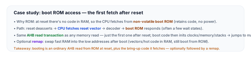
- The path — reset deasserts → CPU fetches from its reset vector → decoder maps the address to the boot ROM → ROM returns the boot code (often a few wait states).
- Same AHB read — it's the same read transaction as any memory read (address phase → data phase), targeting the ROM. The novelty is only that it's the first after reset.
- Then bring-up (+ optional remap) — the boot code initializes the system (clocks, memory, stacks) and jumps to main; some systems remap fast RAM into the low addresses afterward.

So the boot-ROM case study shows that booting is not special at the protocol level — it's an ordinary AHB read, just the first one, from ROM. The value of tracing it is demystifying boot: many engineers think "boot" is some magic — but on the bus, it's the CPU reading instructions from a slave, exactly like any fetch, with the only differences being (a) it's the first transaction after reset, (b) it targets non-volatile ROM (so there's code to fetch before RAM is set up), and (c) ROM may be slower (wait states). The system-level story (the bring-up code, the remap) is what the fetched code does — not a protocol difference. So this case study demystifies boot. So booting is an ordinary read from ROM at reset.
2. Why Does It Exist?
This case study exists because every system must boot (it's a universal, mandatory path) — and because it demystifies boot (showing it's an ordinary AHB read, not magic) — and because it introduces the non-volatile-vs-volatile memory distinction and the remap concept that shape the address map.
The every system must boot is the root: every chip, on power-up, must start executing code — and that code must come from somewhere. So the boot fetch is a universal, mandatory transaction — every system does it, first. So understanding it is essential. So this case study exists to cover the universal boot path. So booting is mandatory. So trace it.
The it demystifies boot is the value: boot is often seen as mysterious — but at the bus level, it's just the CPU reading instructions from a slave. So this case study demystifies it — showing the first fetch is an ordinary AHB read. So it exists to remove the mystery. So it's the demystification. So see the ordinary read.
The non-volatile memory and remap shape the map is the concept: the boot fetch requires non-volatile ROM (RAM is empty at reset), and the remap optimizes the running system (fast RAM at the low addresses). So this case study introduces the non-volatile/volatile distinction and the remap — concepts that shape the address map. So it exists to introduce these map-shaping concepts. So it's the memory-map lesson. So understand ROM/RAM and remap. So this case study exists because: every system must boot (a universal path — the root); it demystifies boot (an ordinary AHB read — the value); and non-volatile memory and remap shape the address map (the concept). So the boot-ROM case study is the universal first transaction — demystified as an ordinary AHB read from non-volatile ROM, introducing the memory-map concepts. So this chapter covers boot. So trace the first fetch, and understand ROM/RAM/remap.
3. Mental Model
Model the boot fetch as waking up in a hotel room with total amnesia, and finding a printed welcome card bolted to the nightstand. You (the CPU at reset) remember nothing — your notebook (RAM) is blank. But the welcome card (boot ROM) is permanently there, printed and bolted down (non-volatile), and it says exactly where to start: "Step 1, call the front desk; step 2, ..." You read the card (fetch from ROM), and it walks you through setting yourself up — get your bearings, write your to-do list in the notebook (initialize RAM), set up your day (configure clocks/stack). Once you're set up, you mostly work from your notebook (run from RAM), only glancing at the card again if you must. The card had to be permanent and bolted down, because a blank notebook can't tell you how to start — you need instructions that survive having no memory.
A hotel room where you wake with total amnesia (the CPU at reset). You remember nothing — your notebook (RAM) is blank (volatile, undefined at power-up). But there's a printed welcome card bolted to the nightstand (the boot ROM) — permanently there, printed and bolted down (non-volatile — retains its contents with no power). It says exactly where to start: "Step 1, ...; Step 2, ..." (the reset vector points into the ROM's boot code). You read the card (the CPU fetches from ROM — an ordinary read), and it walks you through setting yourself up: get your bearings, write your to-do list in the notebook (initialize RAM), set up your day (configure clocks, the stack). Once you're set up, you mostly work from your notebook (run from RAM) — only glancing at the card again if you must. The card had to be permanent and bolted down, because a blank notebook can't tell you how to start — you need instructions that survive having no memory (non-volatile boot code, because RAM is empty at reset).
This captures the boot fetch: waking with amnesia, blank notebook = the CPU at reset with empty RAM; the permanent bolted-down welcome card = the non-volatile boot ROM; the card telling you where to start = the reset vector pointing into the ROM's boot code; reading the card = the CPU fetching from ROM (an ordinary AHB read); writing your to-do list in the notebook, setting up your day = the boot code initializing RAM, clocks, the stack; then working from your notebook = running from RAM (optionally after a remap); the card needing to be permanent = the ROM needing to be non-volatile (RAM is empty at reset). Read the permanent card (fetch from non-volatile ROM), set yourself up (bring-up), then work from your notebook (RAM) — because a blank notebook can't tell you how to begin.
Here is the boot fetch traced, with ROM wait states:
The reset boot fetch — the first AHB read, from boot ROM (with ROM wait states)
5 cyclesThe model's lesson: read the permanent card (fetch from non-volatile ROM), set yourself up (bring-up), then work from your notebook (RAM). In the figure, the boot fetch is an ordinary AHB read — the only novelties are that it's the first (right after HRESETn deasserts), it targets the ROM, and the ROM is slower (a couple of wait states). The system comes alive from there.
4. Real Hardware Perspective
The substance behind the trace is the read and decode structure you've learned — so each step maps to a chapter, applied to the boot path.
The the read and the decode: in hardware — the boot fetch is an AHB read (the same as a memory read); the decoder maps the reset-vector address to the boot ROM (the ROM is placed at the reset-vector address). So the trace applies the read and decode structure (see CPU to SRAM, Address Decoding, HSEL). So it's the read + routing. So fetch, decode to ROM.
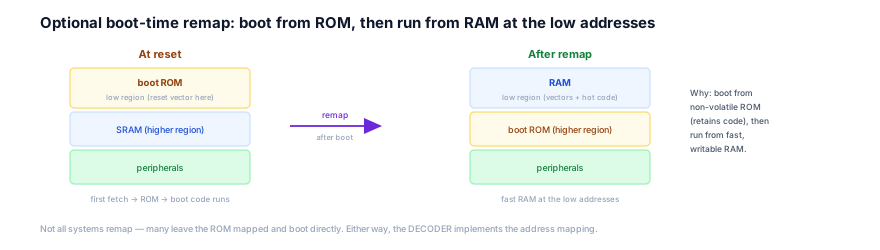
The the ROM slave and the remap: in hardware — the boot ROM is an AHB slave (often slower, inserting wait states); the remap changes the decoder's mapping (RAM into the low region). So the trace applies the slave/HREADY and decode structure (see Memory Slave, What HREADY Means, Default Slave). So in practice, the boot path is the read and decode structure applied — an ordinary read from non-volatile ROM, the decoder routing it, the ROM possibly slow, and an optional remap. So in practice, know the read/decode structure and trace the boot path. So that's the boot path.
5. System Architecture Perspective
At the system level, the boot path anchors the memory map — the boot ROM must be at the reset vector (so the CPU finds code), and the non-volatile/volatile split (ROM for boot, RAM for runtime) plus the optional remap organize the whole address space around how the system starts and runs.
The the boot ROM anchors the map: the CPU's reset vector is fixed (architecture-defined), so the boot ROM must be mapped there — that's a hard constraint on the address map. So the boot requirement anchors the map (the ROM's location is not free). So at the system level, the boot path constrains the map. So place the ROM at the reset vector. So it's a map anchor.
The non-volatile/volatile and remap organize the space: the address map reflects the memory hierarchy — non-volatile ROM/flash (for boot and persistent code/data) and volatile RAM (for runtime). The remap optimizes the running layout (fast RAM at the low addresses). So at the system level, the boot path introduces the organizing principles of the map. So organize ROM/RAM/remap. So it's the map structure. So at the system level, the boot path anchors the memory map (the boot ROM at the reset vector — a hard constraint) and the non-volatile/volatile split plus the remap organize the address space (around how the system starts and runs). So the boot path is where the memory map's structure originates — making the boot ROM's placement and the ROM/RAM/remap organization the keys to a coherent address map. So anchor the ROM, organize the space, optionally remap. So the boot path shapes the map.
6. Engineering Tradeoffs
Tracing the boot path surfaces the boot/memory-map design points.
- Non-volatile ROM vs volatile RAM for boot. Boot must come from non-volatile memory (RAM is empty at reset). ROM/flash retains code; RAM doesn't. Boot from ROM.
- ROM speed vs SRAM speed. ROM/flash is often slower (wait states); SRAM is fast. So you boot from ROM but run hot code from RAM (copied or remapped) for speed.
- Remap vs direct boot. A remap (RAM to the low addresses after boot) gives fast vectors/code; direct boot (leave ROM mapped) is simpler. Choose by whether vector/code speed matters.
- Reset-vector placement. The boot ROM must be at the reset vector (a fixed constraint); the rest of the map is freer. Anchor the ROM there.
The throughline: the boot fetch is an ordinary AHB read — the first after reset, from non-volatile boot ROM (which retains code with no power). Reset deasserts → the CPU fetches its reset vector → the decoder maps it to the boot ROM → the ROM returns the boot code (often a few wait states). The boot code initializes the system (clocks, memory, stacks) and jumps to main; some systems remap fast RAM into the low addresses after. At the system level, the boot path anchors the memory map (ROM at the reset vector) and the ROM/RAM/remap organization structures the address space.
7. Industry Example
A concrete trace — a microcontroller booting from on-chip flash.
A microcontroller powers on. Its boot code lives in on-chip flash (a non-volatile boot ROM), mapped at the reset vector; its RAM is SRAM.
- Reset deasserts. Power and clocks stabilize, and the reset is released. The CPU comes out of reset and prepares to fetch its first instruction from the reset vector address.
- The first fetch targets the boot ROM. The CPU drives the reset-vector address on
HADDRwithHWRITElow — an instruction fetch. The decoder sees the address falls in the boot ROM's region and asserts the ROM'sHSEL. - The ROM responds with wait states. Flash is slower than SRAM, so the boot ROM holds
HREADYlow for a wait state or two while it reads, then drivesHREADYhigh with the first boot instruction onHRDATA. The CPU captures it. - The boot code runs the bring-up. The CPU executes the fetched boot code, which configures the clocks (bringing up the PLL to full speed), initializes the SRAM and the stack pointer, copies initialized data from flash to SRAM, and zeroes the BSS.
- Optional remap. The system may remap: it swaps SRAM into the low addresses so the exception vectors and hot code run from fast SRAM, while flash (still holding the program) moves to or stays at its own region. Or it leaves flash mapped and runs directly from it (possibly with a flash accelerator/cache to hide the wait states).
- Jump to main. Finally, the boot code jumps to the application's entry point, and the system is running its real program — fetching code (from flash or remapped RAM), accessing data, and talking to peripherals.
The example shows the boot path in action: the first fetch is an ordinary AHB read from non-volatile flash at the reset vector (with wait states), and the fetched boot code brings up the system and jumps to main. Booting is demystified — it's reading instructions from a slave, just first, from ROM.
8. Common Mistakes
9. Interview Insight
The boot path is the demystifier — tracing it (first fetch after reset, from non-volatile ROM at the reset vector, an ordinary AHB read) shows you understand how a system starts at the bus level.
If asked how a system boots over AHB, demystify it: at reset, RAM is empty, so the CPU fetches its first instructions from non-volatile boot ROM mapped at the reset vector; the fetch is an ordinary AHB read (address phase → data phase, possibly with wait states since ROM is slower); the boot code then initializes the system (clocks, memory, stacks) and jumps to main; and some systems remap fast RAM into the low addresses afterward. Stress that booting isn't a special protocol mode — it's the CPU reading instructions from a slave, just the first one, from ROM. That shows you understand system bring-up concretely — and the memory-map constraints (ROM at the reset vector, non-volatile for boot, optional remap) that organize the address space.
10. Practice Challenge
Practice tracing the boot path.
- The first fetch. Trace the reset boot fetch — reset deasserts, CPU fetches the reset vector, decoder → boot ROM, ROM responds (with wait states).
- Why ROM. Explain why boot code must come from non-volatile ROM (RAM is empty at reset).
- The reset vector. Explain why the boot ROM must be at the reset vector (a fixed constraint).
- The bring-up. List what the boot code does (clocks, memory, stack, copy data) before jumping to main.
- The remap. Explain a boot-time remap (RAM into the low addresses) and why a system would do it.
11. Key Takeaways
- Boot ROM access is the CPU's first instruction fetch after reset — from non-volatile boot ROM (which retains code with no power), because RAM is empty at reset.
- It's the same AHB read transaction — reset deasserts → CPU fetches its reset vector → decoder maps it to the boot ROM → ROM returns the boot code (often a few wait states). The novelty is only that it's the first, from ROM.
- The boot ROM must be at the reset vector — a fixed constraint (the CPU is hardwired to start there). The ROM's location anchors the memory map.
- ROM is often slower than SRAM — so systems boot from ROM but run hot code from fast RAM (copied or remapped).
- The boot code does the bring-up — configures clocks, initializes memory and the stack, copies data, then jumps to main. It's software in the ROM, delivered by an ordinary read.
- Optional remap — swap fast RAM into the low addresses after boot (for fast, writable vectors/code) — implemented by the decoder.
12. What Comes Next
You can now trace the boot path. The next case studies cover more of the system:
- Debug Subsystem (next) — how a debug access port reaches the AHB fabric (a debug master).
- Microcontroller Bus Fabric and Low-Power Peripheral Access — assembling a full MCU fabric, and gated low-power access.
To revisit the structure this trace applies, see CPU to SRAM, Address Decoding, Memory Slave, HSEL, and What HREADY Means.