A timer peripheral is a down-counter wrapped in a CSR block, and almost everything subtle about it lives in when the counter reloads. You have learned the APB slave interface and the register-design vocabulary — RW config, RO status, W1C clear, write-only triggers. A timer is where all of it lands in one real, shippable block: a value you write (TimerLoad), a count you read (TimerValue), a control word that picks the mode (TimerControl), an interrupt you clear by writing (TimerIntClr), and a background load (TimerBGLoad) that changes the period without kicking the counter mid-flight. We ground this in the Arm SP804 dual-timer register map — a part you will meet in real SoCs — and the single non-obvious idea to carry is the BGLoad vs Load distinction: writing Load restarts the current period from a new value; writing BGLoad changes the next period's reload value while letting the in-flight count run undisturbed to zero. Confuse the two and you ship a timer that glitches its period every time firmware retunes it.
1. Problem statement
The problem is building a programmable down-counter that firmware drives entirely through an APB register interface — start it, pick its mode, time an interval, take an interrupt, and re-time it on the fly — without ever disturbing a count that is mid-flight.
A timer looks trivial: load a number, count down, interrupt at zero. The engineering is in the corners that a one-line description hides:
- It must be fully programmable over the bus. Everything — the load value, the enable, the mode, the prescale divider, the counter width, the interrupt enable and mask — is a field firmware writes through APB. So the timer is, first, a CSR block: a register map with mixed access types decoded off
PADDR, committed offPSEL && PENABLE && PWRITE, read back through a data mux. - It has three distinct counting personalities. One-shot counts down once and stops. Periodic counts down, reloads from
Load, and repeats. Free-running ignoresLoadat zero and wraps through the full counter width. These are not three timers — they are one down-counter whose reload-and-stop behaviour is selected byTimerControlbits. - Re-timing must not glitch the in-flight period. This is the real problem. Firmware that wants to change a periodic timer's interval has two registers it could write:
TimerLoad, which immediately reloads the counter and restarts the current period from the new value (a visible glitch — the current interval is cut short or stretched), orTimerBGLoad, which writes the reload register only, so the in-flight count finishes its current period normally and the new value takes effect at the next zero crossing. Picking the wrong one is the classic timer bug. - The interrupt must be a clean, software-clearable event. At zero the timer raises a raw interrupt; masked by the interrupt-enable it becomes the line the CPU sees. Software clears it by writing a clear register (write-only, W1C) — not by reading, not by writing the count — and that clear must deassert the masked interrupt deterministically.
So the job is not "count down." It is to wrap a prescaled down-counter in an APB CSR interface that exposes load, value, control, and interrupt-clear registers, supports three modes, and — the load-bearing part — separates the reload value from the live count so the period can be retuned without a glitch.
2. Why previous knowledge is insufficient
This module taught the register vocabulary; the timer is the first chapter where you must assemble that vocabulary into a real peripheral with live, self-changing state — and the assembly raises a problem none of the building-block chapters faced.
- CSR fundamentals typed registers in isolation. It taught RW, RO, WO, W1C as independent access contracts. A timer forces them to interact:
TimerValue(RO) is a live image of a counter thatTimerLoad(RW) seeds,TimerControl(RW) gates, andTimerIntClr(WO/W1C) reacts to. The hard part is the coupling between registers, not any one register's access type. - Status registers taught W1C for static event flags. The timer's
RIS/MIS/IntClrare exactly that mechanism — but driven by a counter reaching zero, with a mask (INTENABLE) between raw and masked. The W1C chapter gave you the clear mechanic; it did not give you the event source (a zero-crossing) or the mask path (raw → masked) that a timer wires up. - Configuration registers treated config as set-once-then-frozen.
TimerControlis configuration — but a timer's config is changed while it runs (retune the period, flip one-shot to periodic), and changing it interacts with a live counter. The "lock it and freeze it" model from that chapter is the wrong frame for a register you reprogram mid-run. - None of them has a register that changes by itself. Every prior register held what software wrote until software wrote again.
TimerValuedecrements every (prescaled) clock with no bus activity at all, and reloads itself at zero. That self-modifying behaviour — and the question of which register feeds the reload — is the genuinely new thing, and it is exactly whereBGLoadvsLoadlives.
The gap is this: prior chapters gave you static registers with clean read/write semantics. A timer is a register block married to an autonomous state machine, where one register (Load/BGLoad) feeds a reload value and another (Value) is the live count, and the whole design turns on keeping those two separable so a retune doesn't disturb a running period. Building that is this chapter.
3. Mental model
The model: a timer is one down-counter with two value registers behind it — a reload register (what the counter restarts from) and the live count (what it is right now) — and every subtle behaviour is a question of which one a write touches and when the reload fires.
Picture three pieces feeding a single counter:
- The reload register holds the period.
TimerLoadwrites it and force-loads the counter immediately;TimerBGLoadwrites only this register, leaving the counter alone. So both writes change "the next period," but onlyLoadalso restarts "the current period." This is the wholeBGLoad-vs-Loaddistinction in one sentence: same destination for the period, different effect on the live count. - The prescaler sits between
PCLKand the counter's decrement.PRESCALEinTimerControlselects divide-by-1, -16, or -256, so one decrement happens every 1, 16, or 256 clocks — stretching the timable range without a wider counter. The counter only ticks on a prescaler tick-enable, not every clock. - The mode logic decides what happens at the zero crossing. Free-running (
MODE=0, the SP804 power-up default): ignore the reload, wrap to all-ones, keep going. Periodic (MODE=1): reload the counter from the reload register and continue. One-shot (ONESHOT=1, overridesMODE): reload nothing, halt the counter, leaveENABLEeffectively spent until reprogrammed.
Three refinements make it precise:
- The interrupt is a separate, latched event hung off the zero crossing. Reaching zero sets the raw interrupt status (
RIS). The maskINTENABLEANDs raw → masked (MIS), which is the actual CPU line. Software clears it by writingTimerIntClr(W1C/WO) — the clear resets the latchedRIS, not the counter. The count and the interrupt are decoupled: the counter keeps running (in periodic/free-running) while the interrupt waits to be serviced. Valueis a read-only window onto the live counter, never a write target. Firmware readsTimerValueto sample the count; it cannot poke it. To change the count you writeLoad. This is the RO contract — a hardware-owned live value exposed for observation only.- One-shot is a trap door, not a mode bit you can casually leave set.
ONESHOT=1makes the timer fire once and stop, overriding periodic. A periodic interrupt that "only fires once" is almost always a staleONESHOTbit — the single most common timer-config bug, and the reason mode bits must be read back and verified.
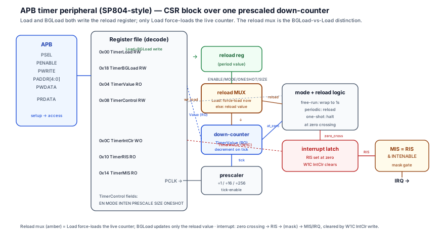
4. Real SoC implementation
The SP804 dual-timer exposes, per timer, the register map below (offsets are within one timer's 0x20 block; the second timer sits at +0x20). This is the real map — load, value, control, three interrupt registers, and the background load.
| Offset | Register | Access | Reset | Purpose |
|---|---|---|---|---|
0x00 | TimerXLoad | RW | 0x0 | Load value; writing it force-loads the counter immediately and restarts the current period |
0x04 | TimerXValue | RO | 0xFFFFFFFF | Live current count — read-only window onto the down-counter |
0x08 | TimerXControl | RW | 0x20 | ENABLE[7], MODE[6] (0=free-run,1=periodic), INTENABLE[5], PRESCALE[3:2] (÷1/÷16/÷256), SIZE[1] (16/32-bit), ONESHOT[0] |
0x0C | TimerXIntClr | WO | — | Write any value to clear the latched interrupt (W1C semantics — the act of writing clears) |
0x10 | TimerXRIS | RO | 0x0 | Raw interrupt status — set at the zero crossing, before masking |
0x14 | TimerXMIS | RO | 0x0 | Masked interrupt status — RIS && INTENABLE; this is the line the CPU sees |
0x18 | TimerXBGLoad | RW | 0x0 | Background load — updates the reload value only, does not force-load the running counter |
The RTL below is the heart of it: APB decode, the prescaled down-counter with the reload mux that distinguishes Load from BGLoad, the TimerControl field decode, and the W1C TimerIntClr against the raw/masked interrupt. Real APB signal names throughout.
// ============================================================
// SP804-style APB timer — one timer instance (0x20 register block)
// ============================================================
//  Offset  Register        Access  Reset        Notes
//  0x00    TimerXLoad      RW      0x0          write force-loads the counter NOW (restarts period)
//  0x04    TimerXValue     RO      0xFFFFFFFF   live down-counter
//  0x08    TimerXControl   RW      0x20         ENABLE/MODE/INTENABLE/PRESCALE/SIZE/ONESHOT
//  0x0C    TimerXIntClr    WO      -            any write clears the latched interrupt (W1C)
//  0x10    TimerXRIS       RO      0x0          raw interrupt (set at zero crossing)
//  0x14    TimerXMIS       RO      0x0          masked interrupt = RIS & INTENABLE
//  0x18    TimerXBGLoad    RW      0x0          updates reload value only (NO force-load)

logic [31:0] load_reg;     // the reload value (period) — written by BOTH Load and BGLoad
logic [31:0] counter;      // the live down-counter — TimerValue reads this
logic [7:0]  ctrl;         // TimerControl
logic        ris;          // raw interrupt latch

// --- TimerControl field decode (real SP804 bit positions) ---
wire        en        = ctrl[7];            // ENABLE
wire        mode      = ctrl[6];            // 0 = free-running, 1 = periodic
wire        int_en    = ctrl[5];            // INTENABLE (mask)
wire [1:0]  prescale  = ctrl[3:2];          // 00:÷1  01:÷16  10:÷256
wire        size32    = ctrl[1];            // 0 = 16-bit, 1 = 32-bit
wire        oneshot   = ctrl[0];            // ONESHOT overrides MODE

// --- APB access decode (write commits in ACCESS phase) ---
wire wr_en   = psel && penable && pwrite;
wire wr_load   = wr_en && (paddr[4:0] == 5'h00);  // TimerLoad
wire wr_ctrl   = wr_en && (paddr[4:0] == 5'h08);  // TimerControl
wire wr_intclr = wr_en && (paddr[4:0] == 5'h0C);  // TimerIntClr (W1C — any write clears)
wire wr_bgload = wr_en && (paddr[4:0] == 5'h18);  // TimerBGLoad

// --- Prescaler: one tick-enable every 1 / 16 / 256 clocks ---
logic [7:0] pre_cnt;
wire [7:0]  pre_max = (prescale == 2'b00) ? 8'd0    // ÷1   -> tick every clock
                    : (prescale == 2'b01) ? 8'd15   // ÷16
                    :                       8'd255;  // ÷256
wire tick = en && (pre_cnt == pre_max);             // counter decrements on tick

always_ff @(posedge pclk or negedge presetn)
  if (!presetn)         pre_cnt <= 8'd0;
  else if (!en)         pre_cnt <= 8'd0;
  else if (pre_cnt == pre_max) pre_cnt <= 8'd0;
  else                  pre_cnt <= pre_cnt + 8'd1;

// --- The reload register: BOTH Load and BGLoad write it, masked by SIZE ---
wire [31:0] wmask = size32 ? 32'hFFFF_FFFF : 32'h0000_FFFF;
always_ff @(posedge pclk or negedge presetn)
  if (!presetn)            load_reg <= 32'h0;
  else if (wr_load)        load_reg <= pwdata & wmask;   // Load updates reload value...
  else if (wr_bgload)      load_reg <= pwdata & wmask;   // ...and so does BGLoad (same dest)

// --- The down-counter: THIS is where Load and BGLoad DIFFER ---
wire at_zero = (counter == 32'h0);
always_ff @(posedge pclk or negedge presetn) begin
  if (!presetn)            counter <= 32'hFFFF_FFFF;     // free-running default at reset
  else if (wr_load)        counter <= pwdata & wmask;    // Load FORCE-LOADS the live count NOW
  // NOTE: wr_bgload is deliberately ABSENT here — BGLoad must NOT disturb the running count.
  else if (tick) begin
    if (at_zero) begin
      if (oneshot)         counter <= counter;           // one-shot: halt at zero, no reload
      else if (mode)       counter <= load_reg;          // periodic: reload from (possibly BG-updated) value
      else                 counter <= wmask;             // free-running: wrap to all-ones
    end else
                           counter <= counter - 32'h1;   // normal decrement
  end
end

// --- TimerControl write ---
always_ff @(posedge pclk or negedge presetn)
  if (!presetn)     ctrl <= 8'h20;                 // reset: free-running, int disabled
  else if (wr_ctrl) ctrl <= pwdata[7:0];

// --- Interrupt: raw latch set at the zero crossing; W1C clear via TimerIntClr ---
wire zero_cross = en && tick && at_zero;          // pulse when counter hits zero on a tick
always_ff @(posedge pclk or negedge presetn)
  if (!presetn)        ris <= 1'b0;
  else if (wr_intclr)  ris <= 1'b0;                // ANY write to IntClr clears the latch (W1C)
  else if (zero_cross) ris <= 1'b1;                // zero crossing latches raw interrupt
wire mis = ris & int_en;                           // masked interrupt = the CPU-visible IRQ
assign timer_irq = mis;

// --- APB read mux: TimerValue / RIS / MIS are read-only live images ---
always_comb unique case (paddr[4:0])
  5'h00:   prdata = load_reg;
  5'h04:   prdata = counter;                       // TimerValue: live count, RO
  5'h08:   prdata = {24'h0, ctrl};
  5'h10:   prdata = {31'h0, ris};                  // RIS, RO
  5'h14:   prdata = {31'h0, mis};                  // MIS, RO
  5'h18:   prdata = load_reg;                       // BGLoad reads back the reload value
  default: prdata = 32'h0;                          // IntClr (WO) reads as 0
endcase
Three facts make this a timer and not a plain counter. First, the reload register and the live counter are two separate flops, and the only structural difference between Load and BGLoad is that wr_load appears in the counter's force-load branch while wr_bgload does not — that single absent line is the entire BGLoad guarantee. Second, the prescaler gates the decrement, not the clock: tick is a one-cycle enable, so the counter sees PCLK but only counts down once per prescale period, which is how a 32-bit counter at ÷256 times very long intervals. Third, the interrupt is latched and decoupled from the count: ris is set by the zero crossing and cleared only by a TimerIntClr write (W1C), so the counter keeps reloading and running in periodic mode while the interrupt patiently waits to be serviced — and mis = ris & int_en means masking happens at the very last gate, exactly as the SP804 RIS/MIS split prescribes. The commit machinery underneath is the ordinary APB write logic and read-data mux; the timer only adds the counter and the reload semantics on top.
5. Engineering tradeoffs
The design decisions in a timer are mostly about which knob to expose and what it costs — and the central one is the Load/BGLoad pair, which exists precisely because force-load and background-load are two genuinely different operations with different uses.
| Decision | Option A | Option B | When to pick which |
|---|---|---|---|
| Retune the period | TimerLoad — force-loads now, restarts the current period | TimerBGLoad — updates reload value only, current period finishes | Use Load to immediately change timing (start fresh, abort current interval); use BGLoad to seamlessly change the next period with no glitch to the in-flight count |
| Counting personality | Periodic — auto-reload at zero, repeats | One-shot — fire once, halt | Periodic for a steady tick (RTOS scheduler, PWM); one-shot for a single timeout (watchdog kick, debounce) |
| Range vs resolution | PRESCALE=÷1 — full clock resolution, short max interval | PRESCALE=÷256 — coarse resolution, 256× longer max interval | Fine resolution for short precise delays; high prescale to time long intervals without a wider counter |
| Counter width | SIZE=16-bit — smaller, shorter max count | SIZE=32-bit — larger range | 16-bit for legacy/compact timers; 32-bit when the interval (even prescaled) needs the range |
| Interrupt visibility | Read RIS (raw) | Read MIS (masked) | RIS to see the event regardless of mask (debug, polling a disabled-interrupt timer); MIS to see exactly what the CPU's interrupt controller sees |
The throughline: Load and BGLoad are not redundant — they are the force-load and the seamless-update of the same period, and choosing wrongly is a functional bug, not a style choice. A scheduler that retunes its tick period with Load introduces a one-time glitch (the current tick is cut short or stretched) every time it changes frequency; the same scheduler using BGLoad changes the period with the current tick finishing cleanly and the new period starting at the next reload — invisible to the timing it controls. The prescale and size knobs trade range against resolution and area; the mode and interrupt knobs trade autonomy (periodic, masked) against control (one-shot, raw-visible). None of these is free, and the spec exposes all of them because real systems need each.
6. Common RTL mistakes
7. Debugging scenario
The signature timer bug is the period glitch from using Load instead of BGLoad to retune a running periodic timer — the timer keeps working, but every frequency change produces a one-shot wrong interval that ripples into whatever the timer paces.
-
Observed symptom: an audio or PWM subsystem driven by a periodic timer produces an audible click or a visible flicker exactly when firmware changes the rate — never otherwise. The timer is clearly running and interrupting at the right new rate afterward; only the transition is wrong. Single-stepping the rate-change code never reproduces it because the glitch is one period long and the debugger's pauses mask it.
-
Waveform clue: the APB trace shows a write to
TimerLoad(PSEL,PENABLE,PWRITEhigh,PADDR = 0x00) carrying the new period — and on that exact cycleTimerValuejumps from its mid-count value straight to the new load value (Figure 2 shows the configuration-then-count sequence this is a corruption of). The current period, which had counted down to, say, 0x340 of an original 0x1000, is abandoned and a fresh 0x800 period starts immediately. The interval between the interrupt before the change and the one after is neither the old period nor the new one — it is a truncated stub. -
Root cause: firmware retuned the period by writing
TimerLoad, which force-loads the live counter, restarting the current period mid-flight. The current interval is cut short (or, if the new value is larger, stretched), producing a single glitched period at every rate change. The reload value and the live count were both changed when only the reload value should have been. -
Correct fix: retune with
TimerBGLoad. It writes the reload register only, so the in-flight count finishes its current period undisturbed and the new period takes effect at the next zero crossing — no glitch, no truncated stub. The RTL guarantee is structural:wr_bgloadupdatesload_regbut is deliberately absent from the counter's force-load branch, so aBGLoadwrite physically cannot perturb the running count. -
Verification assertion: prove
BGLoadnever disturbs the live counter, and proveLoaddoes:Azvya Education Pvt. Ltd.VLSI MentorSnippet// BGLoad updates the reload value but must NOT change the live count this cycle. property bgload_no_count_disturb; @(posedge pclk) disable iff (!presetn) wr_bgload |=> $stable(counter) || (tick && !$past(at_zero)); endproperty assert property (bgload_no_count_disturb); // Load force-loads: the cycle after a Load write, counter equals the loaded value. assert property (@(posedge pclk) disable iff (!presetn) wr_load |=> (counter == $past(pwdata & wmask))); -
Debug habit: when a timer-paced subsystem glitches only at a rate change and runs perfectly otherwise, do not chase the counter logic — chase which register firmware writes to retune. Open the rate-change routine and check the offset:
0x00(Load) force-loads and glitches;0x18(BGLoad) is seamless. The "glitches only on transition" signature almost always meansLoadwas used whereBGLoadwas required.
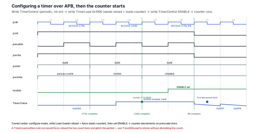
8. Verification perspective
A timer is verified by proving the autonomous behaviour — the counter and interrupt that move with no bus activity — matches the register-programmed intent, with the highest-value properties sitting on the reload semantics, the mode transitions, and the W1C interrupt clear.
-
LoadresetsValue;BGLoaddoes not. The two anchor properties. ATimerLoadwrite must force the counter to the written value next cycle; aTimerBGLoadwrite must leave the live counter undisturbed (it only updates the reload register). These are the properties that catch the period-glitch bug and the inverse — aLoadthat fails to force-load:Azvya Education Pvt. Ltd.VLSI MentorSnippet// Writing TimerLoad force-loads the counter (Value reflects the new load). assert property (@(posedge pclk) disable iff (!presetn) wr_load |=> (counter == $past(pwdata & wmask))); // Writing TimerBGLoad updates the reload value but does NOT reload the live count. assert property (@(posedge pclk) disable iff (!presetn) (wr_bgload && !(tick && at_zero)) |=> $stable(counter)); -
Periodic reload at zero; one-shot halt at zero. Prove that in periodic mode (
MODE=1, ONESHOT=0) the counter reloads fromload_regon the tick after it hits zero, and in one-shot (ONESHOT=1) it stays at zero. This is the mode-transition coverage that catches a staleONESHOTmasquerading as periodic:Azvya Education Pvt. Ltd.VLSI MentorSnippet// Periodic: at a zero-crossing tick, the counter reloads from the reload register. assert property (@(posedge pclk) disable iff (!presetn) (en && tick && at_zero && mode && !oneshot) |=> (counter == $past(load_reg))); -
TimerIntClrdeassertsMIS; the zero crossing assertsRIS. Prove the W1C clear path: a write toTimerIntClrmust clearRIS(and thereforeMIS) the next cycle, and a zero crossing with the timer enabled must setRIS. Pair with a never-X check on the IRQ:Azvya Education Pvt. Ltd.VLSI MentorSnippet// A TimerIntClr write clears the raw interrupt -> masked interrupt deasserts. assert property (@(posedge pclk) disable iff (!presetn) wr_intclr |=> !ris); // The zero crossing latches the raw interrupt. assert property (@(posedge pclk) disable iff (!presetn) zero_cross |=> ris); -
Prescale and coverage. Cover all three
PRESCALEsettings (÷1/÷16/÷256) crossed with bothSIZEwidths and all three modes, and assert that the counter decrements exactly once per prescale period (not every clock). The high-value cross is{periodic, one-shot, free-run} × {÷1, ÷16, ÷256} × {Load-retune, BGLoad-retune}— the corner where aLoad/BGLoadmistake hides is a mid-run retune in periodic mode, so it must be an explicit bin, not left to random.
The point: the timer's hard properties are about self-changing state. Verify that the counter reloads when and only when it should, that Load and BGLoad differ exactly at the live count, and that the interrupt sets at zero and clears on the W1C write — not just that you can read the registers back. The APB assertions and monitors of the verification module are the substrate these timer-specific properties bind onto.
9. Interview discussion
"Walk me through an APB timer peripheral, and tell me the difference between Load and BGLoad" is a favourite because the first half checks whether you can assemble a CSR block, and the second half — the Load/BGLoad distinction — separates people who have integrated a real timer from those who have only read "it counts down."
Lead with the structure: a timer is a prescaled down-counter wrapped in an APB register file — TimerLoad (the reload value, RW, force-loads on write), TimerValue (the live count, RO), TimerControl (ENABLE/MODE/INTENABLE/PRESCALE/SIZE/ONESHOT), TimerIntClr (W1C clear), RIS/MIS (raw and masked interrupt), and TimerBGLoad (background reload). Name the three personalities crisply — free-running wraps, periodic auto-reloads, one-shot fires once and halts (and ONESHOT overrides MODE). Then deliver the depth point that signals real silicon work: Load and BGLoad write the same reload register, but Load also force-loads the live counter and restarts the current period, while BGLoad updates only the reload value so the in-flight period finishes cleanly and the new period starts at the next zero crossing. Give the consequence: retuning a running periodic timer with Load glitches one period (the current interval is truncated); BGLoad retunes seamlessly. Land two more experience markers — a periodic interrupt that fires once is a stale ONESHOT bit, and the interrupt is cleared by writing TimerIntClr (W1C), never by reading the value — and note the masking split (MIS = RIS && INTENABLE, so poll RIS to see events on a masked timer). Closing with "the BGLoad-vs-Load split is the whole reason the SP804 has two load registers — one to restart, one to retune without disturbing the count" shows you understand why the map is shaped the way it is, not just what the bits are.
10. Practice
- Trace the reload mux. Given
load_reg = 0x1000andcounter = 0x340mid-count, state the resultingcounternext cycle for (a) aTimerLoadwrite of0x800, and (b) aTimerBGLoadwrite of0x800. Explain which one glitches the period and why. - Decode the control word. Given
TimerControl = 0x67, decode every field (ENABLE, MODE, INTENABLE, PRESCALE, SIZE, ONESHOT) and state how the timer behaves at the next zero crossing. - Find the stale ONESHOT. A periodic timer interrupts exactly once and then never again, though it stays enabled. Name the bug, the exact
TimerControlbit, and how you would confirm it from a register read. - Write the W1C clear. Write the SVA that proves a
TimerIntClrwrite deassertsMISnext cycle, and a separate property that the zero crossing setsRIS. State why readingTimerValuemust not clear the interrupt. - Choose the prescale. You must time a 1-second interval from a 50 MHz
PCLKwith a 32-bit counter. State whether ÷1, ÷16, or ÷256 is needed and roughly the load value, and explain the resolution you give up at the higher prescale.
11. Q&A
12. Key takeaways
- A timer peripheral is a prescaled down-counter wrapped in an APB CSR block —
TimerLoad/Value/Control/IntClr/RIS/MIS/BGLoad— where the registers configure and observe an autonomous counter that changes itself every (prescaled) clock and reloads at zero. LoadvsBGLoadis the load-bearing distinction: both write the same reload register, butTimerLoadalso force-loads the live counter and restarts the current period, whileTimerBGLoadupdates only the reload value so the in-flight period finishes cleanly and the new period starts at the next zero crossing — useBGLoadto retune a running timer without a glitch.- Three modes, one counter: free-running wraps to all-ones, periodic auto-reloads from
Load, one-shot fires once and halts — andONESHOToverridesMODE, so a periodic interrupt that fires only once is almost always a staleONESHOTbit. - The interrupt is a latched event, cleared by a write, not a read: the zero crossing sets
RIS,INTENABLEmasks it intoMIS(the CPU line), and a W1C write toTimerIntClrclears it — readingTimerValueorRISnever clears it. - The prescaler gates the decrement, not the clock:
PRESCALEselects ÷1/÷16/÷256 so the counter ticks once per prescale period, trading resolution for range without a wider counter; verify it decrements once per period, not everyPCLK. - Verify the self-changing state: prove
LoadresetsValueandBGLoaddoes not, that periodic reloads at zero and one-shot halts, and thatTimerIntClrdeassertsMIS— built on the APB assertions and monitors substrate. (Sources: Arm SP804 Dual-Timer Technical Reference Manual; AMBA APB Protocol Specification, IHI 0024C, §2.1.)