An interrupt controller is a register map first and a piece of logic second — and its hardest design decision is how software enables and disables one source without a read-modify-write that can lose another. A vectored interrupt controller (VIC) sits between a swarm of peripheral interrupt lines and the CPU's nIRQ / nFIQ inputs, and software programs every part of it — which sources are enabled, which are routed to IRQ versus the faster FIQ, and which it wants to fire by hand — through APB control and status registers (CSRs). This chapter grounds that map in the real Arm PrimeCell PL190 VIC, and the single non-trivial idea to carry through it is the paired set/clear register idiom: the PL190 exposes the same enable bits at two different addresses — one where writing a 1 sets an enable (VICIntEnable) and one where writing a 1 clears it (VICIntEnClear) — so software can enable or disable exactly one interrupt with a single write, never reading the register first, never stamping a stale value back over a bit another context just changed. That idiom is the reason this map is correct under concurrency, and it is the thing most home-grown interrupt controllers get wrong.
1. Problem statement
The problem is multiplexing many peripheral interrupt lines down to a CPU's one or two interrupt inputs, under full software control, through a register interface that stays correct when more than one piece of software touches it.
A SoC has dozens of interrupt sources — timers, UARTs, DMA channels, a watchdog — and a CPU with a single nIRQ line (and usually one faster nFIQ). Something must combine them, let software choose which ones are allowed to interrupt, choose which go to the fast path, report which are pending, and let software raise an interrupt by hand for inter-process signalling. All of that is programmable, which means it lives in a register map reached over APB. Three forces make the map design non-trivial:
- Per-source enable must be selective and atomic. Software wants to enable interrupt 7 without disturbing the enable state of the other 31 sources. With a single plain read-write enable register, "enable bit 7" is a read-modify-write: read all 32 enables, OR in bit 7, write back. If an interrupt fires during that sequence and its ISR enables a different bit, the outer write stamps the stale word back and silently disables the bit the ISR just enabled. The map must make a single-bit enable/disable a one-shot write that cannot lose a concurrent change.
- The raw event and the enable decision are different facts. Whether source
iis asserting (raw) and whether software wants to hear it (enable) are independent. So is which CPU input it routes to (IRQ vs the higher-priority FIQ). The map must expose each of these separately so software can read raw lines, program enables, and program routing without conflating them. - Software interrupts are first-class. Software must be able to assert an interrupt source itself — for doorbell / inter-processor signalling — and clear it, again without read-modify-write.
So the job is to lay out a register map that exposes the raw → select → enable → status path, supports software-asserted interrupts, and — the crux — makes single-source enable/disable atomic. This is a CSR-design problem layered on top of the status-register family, specialised for an interrupt controller.
2. Why previous knowledge is insufficient
The status-registers chapter built the canonical interrupt structure — sticky raw status, an enable/mask, and irq = OR(raw & enable) — and that is the backbone of this controller. But a real VIC adds three things that backbone does not describe.
- A single plain RW enable register is not enough — it forces a read-modify-write. The status-registers chapter kept the mask as one ordinary RW register, which is fine when one agent owns it. A real interrupt controller is touched by many contexts (the kernel, several ISRs, sometimes another CPU), and "enable just this one source" via a plain RW register is an RMW that races. The PL190's answer — the paired set/clear registers — is a map-level idea that none of the prior CSR chapters covered. This chapter adds it, and it is the whole point.
- Routing (IRQ vs FIQ) is a second classification axis the backbone ignores. The status backbone has one output. A VIC has two — a normal
nIRQand a fast, higher-prioritynFIQ— and a per-sourceVICIntSelectregister decides which line each source drives. That select sits between raw and enable in the data path and changes the status equation, and it has no analogue in the simple raw/mask/irq model. - The raw input itself is exposed, and so is a software override. The PL190 exposes
VICRawIntr(the raw lines before enable) andVICSoftInt(a register where software can force a source active). Neither is in the basic status model. The raw view is essential for polling masked sources; the soft-interrupt path is essential for doorbells.
So the model to add is the full PL190 register map — raw, select, the paired enable set/clear, software-interrupt set/clear, and masked status — and the register-map layout discipline that makes the set/clear pairing safe. The read-only-registers and write-only-registers chapters describe the individual access types each of these registers uses; this chapter assembles them into a working controller.
3. Mental model
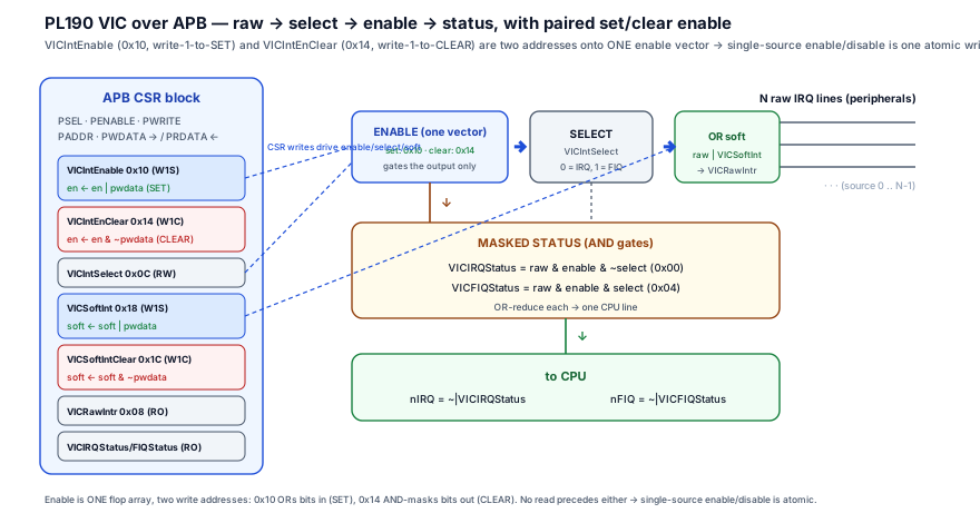
The model: a VIC is a four-stage pipeline from raw lines to CPU inputs — raw → select → enable → status — and the APB register map is a set of windows and levers onto that pipeline, with the enable lever deliberately split into two one-way buttons.
Walk the data path of one source i:
- Raw. The peripheral drives a level interrupt line.
VICRawIntr[i]is a read-only window onto that raw line before any masking — software can always see what is asserting, even sources it has disabled. (Raw also folds in any software-asserted interrupt, below.) - Select.
VICIntSelect[i]is a per-source lever:0routes the source to the normalnIRQpath,1routes it to the fastnFIQpath. It classifies, it does not gate. - Enable.
VICIntEnable[i]decides whether sourceiis allowed to reach a CPU line at all. This is the lever that is split: there is no single writable enable register. InsteadVICIntEnable(write-1-to-SET) andVICIntEnClear(write-1-to-CLEAR) are two addresses onto the same physical enable bits — a "turn on" button and a "turn off" button. Reading either returns the current enable state. - Status. The masked IRQ status is
VICIRQStatus[i] = raw[i] & enable[i] & ~select[i](a source that is enabled, asserting, and routed to IRQ). The FIQ status is the symmetricraw[i] & enable[i] & select[i].nIRQasserts when anyVICIRQStatusbit is set;nFIQwhen anyVICFIQStatusbit is set.
The two refinements that make this a controller and not just a mask:
- The split enable is the model's centrepiece. A "set" register and a "clear" register onto one set of bits means enable source 7 is the single write
VICIntEnable = (1 << 7)and disable source 7 is the single writeVICIntEnClear = (1 << 7)— each touches exactly its own bit, leaves the other 31 untouched, and requires no prior read. Because there is no read-modify-write, two contexts can enable two different sources concurrently and neither can clobber the other. That atomicity is the entire reason the idiom exists. - Software interrupts ride the same pipeline.
VICSoftInt(write-1-to-set) lets software force a source active exactly as if its peripheral had asserted;VICSoftIntClear(write-1-to-clear) retracts it. The forced bit ORs into the raw line, so it flows through select/enable/status like any hardware source — a doorbell with no extra logic.
4. Real SoC implementation
The PL190 register map is the concrete contract. Every offset below is real; the access types are what make the controller work — note especially the two pairs of set/clear registers (enable and software-interrupt) that read back the same state they write into.
| Offset | Register | Access | Reset | Purpose |
|---|---|---|---|---|
0x00 | VICIRQStatus | RO | 0x0 | Masked IRQ status: raw & enable & ~select. Bits routed to IRQ that are enabled and asserting. |
0x04 | VICFIQStatus | RO | 0x0 | Masked FIQ status: raw & enable & select. Bits routed to FIQ that are enabled and asserting. |
0x08 | VICRawIntr | RO | — | Raw interrupt status before enable/select — every source asserting (incl. software-asserted), masked or not. |
0x0C | VICIntSelect | RW | 0x0 | Per-source route select: 0 = IRQ, 1 = FIQ. |
0x10 | VICIntEnable | RW (write-1-to-SET) | 0x0 | Enable register — write 1 to enable a source; writing 0 has no effect. Reads back current enables. |
0x14 | VICIntEnClear | WO (write-1-to-CLEAR) | — | Clears enables — write 1 to disable the same bits as VICIntEnable; writing 0 has no effect. |
0x18 | VICSoftInt | RW (write-1-to-SET) | 0x0 | Software interrupt — write 1 to force a source active. Reads back current software-asserted bits. |
0x1C | VICSoftIntClear | WO (write-1-to-CLEAR) | — | Clears software interrupts — write 1 to retract the same bits as VICSoftInt. |
0x30 | VICVectAddr | RW | 0x0 | ISR address of the currently active interrupt; reading it also signals interrupt entry to priority logic. |
0x34 | VICDefVectAddr | RW | 0x0 | Default ISR address used for non-vectored (default) interrupts. |
The non-obvious rows are 0x10/0x14 (and 0x18/0x1C): two addresses, one set of physical bits. The decode below implements that paired set/clear enable, plus the masked-status read.
// ---- PL190-style VIC register decode on an APB slave -------------------
//  APB CSR signals: pclk, presetn, psel, penable, pwrite, paddr[7:0],
//                   pwdata[31:0], prdata[31:0].  N = number of sources.
//
//  Map contract (real PL190 offsets):
//    0x08 VICRawIntr   RO   raw (incl. software-asserted) lines
//    0x0C VICIntSelect RW   per-source 1 = FIQ, 0 = IRQ
//    0x10 VICIntEnable  W1S  write 1 SETS an enable  (reads back enables)
//    0x14 VICIntEnClear W1C  write 1 CLEARS the SAME enables
//    0x18 VICSoftInt    W1S  write 1 forces a source active
//    0x1C VICSoftIntClear W1C write 1 retracts it
//    0x00 VICIRQStatus RO   raw & enable & ~select
//    0x04 VICFIQStatus RO   raw & enable &  select

logic [N-1:0] int_enable;   // the ONE physical enable vector...
logic [N-1:0] int_select;   // 1 = route to FIQ, 0 = IRQ
logic [N-1:0] soft_int;     // software-asserted sources

// a qualified APB write strobe: data phase of a write to this slave
wire          wr      = psel & penable & pwrite;
wire [N-1:0]  wdata_n = pwdata[N-1:0];

// raw line = hardware request OR software-asserted request (PL190 folds soft in)
wire [N-1:0]  raw_intr = irq_src_i | soft_int;   // irq_src_i = N level inputs

// ---- PAIRED set/clear ENABLE: two addresses, ONE bit vector ----------
// Write-1-to-SET at 0x10 and write-1-to-CLEAR at 0x14 onto int_enable.
// No read-modify-write: each write touches only the bits whose pwdata = 1.
always_ff @(posedge pclk or negedge presetn) begin
  if (!presetn)
    int_enable <= '0;                                   // reset: all disabled
  else if (wr && paddr[7:0] == 8'h10)
    int_enable <= int_enable |  wdata_n;                // SET  (VICIntEnable)
  else if (wr && paddr[7:0] == 8'h14)
    int_enable <= int_enable & ~wdata_n;                // CLEAR (VICIntEnClear)
  // else hold — enables persist; one source's write never disturbs another's bit
end

// ---- PAIRED set/clear SOFTWARE INTERRUPT (same idiom) ----------------
always_ff @(posedge pclk or negedge presetn) begin
  if (!presetn)
    soft_int <= '0;
  else if (wr && paddr[7:0] == 8'h18)
    soft_int <= soft_int |  wdata_n;                    // SET  (VICSoftInt)
  else if (wr && paddr[7:0] == 8'h1C)
    soft_int <= soft_int & ~wdata_n;                    // CLEAR (VICSoftIntClear)
end

// ---- SELECT: a plain RW register (IRQ vs FIQ routing) ----------------
always_ff @(posedge pclk or negedge presetn)
  if (!presetn)                              int_select <= '0;
  else if (wr && paddr[7:0] == 8'h0C)        int_select <= wdata_n;

// ---- MASKED STATUS and the two CPU lines -----------------------------
wire [N-1:0] irq_status = raw_intr & int_enable & ~int_select;  // 0x00
wire [N-1:0] fiq_status = raw_intr & int_enable &  int_select;  // 0x04
assign n_irq = ~(|irq_status);   // active-low: assert when any IRQ source pending
assign n_fiq = ~(|fiq_status);   // active-low: assert when any FIQ source pending

// ---- READ MUX ---------------------------------------------------------
always_comb unique case (paddr[7:0])
  8'h00:   prdata = {{(32-N){1'b0}}, irq_status};  // VICIRQStatus  (masked IRQ)
  8'h04:   prdata = {{(32-N){1'b0}}, fiq_status};  // VICFIQStatus  (masked FIQ)
  8'h08:   prdata = {{(32-N){1'b0}}, raw_intr};    // VICRawIntr    (raw)
  8'h0C:   prdata = {{(32-N){1'b0}}, int_select};  // VICIntSelect
  8'h10:   prdata = {{(32-N){1'b0}}, int_enable};  // ENABLE reads back current state
  8'h18:   prdata = {{(32-N){1'b0}}, soft_int};    // VICSoftInt reads back soft bits
  default: prdata = 32'h0;
endcase
Three facts make this interrupt-controller design, not generic register decode. First, VICIntEnable and VICIntEnClear are one flop array reached through two address-decoded write paths — a write-1-to-set at 0x10 ORs bits in, a write-1-to-clear at 0x14 masks bits out, and a read of either returns int_enable. That is what removes the read-modify-write: enabling source 7 is *VICIntEnable = (1<<7) and disabling it is *VICIntEnClear = (1<<7), each touching exactly one bit. Second, the masked status is computed live from raw & enable & ~select (and the FIQ symmetric), so VICIRQStatus is a pure read-only view of the pipeline — it has no state of its own and the CPU line is just its OR-reduce. Third, the software-interrupt pair uses the identical idiom, and because soft_int ORs into raw_intr, a software-asserted source flows through select and enable exactly like a hardware one — the doorbell needs no special status path.
5. Engineering tradeoffs
The design decision specific to an interrupt controller is how to expose the enable bits. The table is the menu, and it is why the PL190 chose paired set/clear over a single RW register.
| Enable exposure | Enable one source | Disable one source | Atomic / race-free? | Notes |
|---|---|---|---|---|
| Single plain RW register | read all enables, OR in the bit, write back (RMW) | read, AND out the bit, write back (RMW) | No — the read-modify-write window can lose a concurrent enable from an ISR or another CPU | Smallest map (one address), but unsafe under concurrency. The bug this whole chapter is about. |
| Paired set / clear (PL190) | VICIntEnable = (1<<i) — one write, sets only bit i | VICIntEnClear = (1<<i) — one write, clears only bit i | Yes — each write affects only the 1-bits in pwdata; no read precedes it | Two addresses for one bit vector. The hardware does the OR/AND-mask; software never reads first. |
| Bit-band / per-bit alias | write 1 to a dedicated single-bit address | write 0 to it | Yes, but at huge address cost | One address per bit per register — 32× the map. Used on some Cortex-M cores, not on the PL190. |
The throughline: paired set/clear trades one extra address per enable register for atomic, read-modify-write-free single-source control — exactly the property an interrupt controller needs because it is touched by many concurrent contexts. The single-RW register saves an address and is fine for a config register one agent owns, but for enables that ISRs flip it is the classic lost-update race. Bit-banding achieves the same atomicity but explodes the map. The PL190's choice is the sweet spot: two addresses, the write-1-to-set / write-1-to-clear semantics put the OR/AND-mask in hardware, and the masked status stays a pure read-only view. Note the asymmetry the table hides: the status/raw path is read-only and the enable/soft path is write-driven-with-readback — exactly the status-register split applied to a controller.
6. Common RTL mistakes
7. Debugging scenario
The signature interrupt-controller bug is a lost interrupt enable caused by a read-modify-write on the enable register — a driver that "enables one source" by reading VICIntEnable, setting a bit, and writing it back, occasionally finding a different source mysteriously disabled afterward.
- Observed symptom: a peripheral that was working stops delivering interrupts intermittently. Its
VICRawIntrbit is asserting (the peripheral is requesting), but itsVICIRQStatusbit is0— the source is not enabled — even though the driver's enable code definitely ran. It correlates with interrupt activity: the more other interrupts are firing, the more often a source ends up disabled. Single-stepping never reproduces it. - Waveform / trace clue: an APB trace shows the enable register being read (a read of
0x10), then later written (a write of0x10) with a value that has the target bit set but a previously-enabled bit cleared. Between the read and the write there is a second APB write to0x10from an ISR enabling its own source. The outer driver's write-back used the value it read before the ISR's write — so it overwrote the ISR's freshly-enabled bit back to 0. - Root cause: the driver treated
VICIntEnableas a plain RW register and used a read-modify-write to set one bit. The RMW is not atomic: an interrupt landed in the window between the read and the write, its ISR enabled a different source by the same (buggy) RMW, and the outer write-back stamped the stale enable word back — destroying the ISR's update. This is a classic lost-update race, and the PL190's paired set/clear design exists precisely to make it impossible. - Correct usage: never read the enable register to modify it. Use the one-way write-1-to-set / write-1-to-clear addresses, each of which touches only the bits set in
pwdata:Azvya Education Pvt. Ltd.VLSI MentorSnippet// WRONG — read-modify-write, races with any concurrent enable: uint32_t en = readl(VIC + 0x10); // VICIntEnable en |= (1u << src); writel(en, VIC + 0x10); // stamps stale word -> lost update // CORRECT — atomic single-bit set/clear, no read: writel((1u << src), VIC + 0x10); // VICIntEnable : enable source `src` writel((1u << src), VIC + 0x14); // VICIntEnClear : disable source `src` - Verification assertion: prove that a write-1-to-clear affects only the addressed bits and that the masked status equals the defined expression — the two properties that catch a decode that accidentally turned the paired registers into a plain RW (see §8).
- Debug habit: when an interrupt "won't enable" intermittently, do not start in the peripheral — first ask "is the driver doing a read-modify-write on the enable register?" If
VICRawIntrshows the source asserting butVICIntEnablereads back with the bit clear right after the enable code ran, you have a lost-update race, and the fix is to switch to the one-wayVICIntEnable/VICIntEnClearwrites the hardware was designed for.
8. Verification perspective
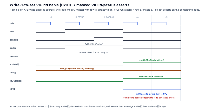
An interrupt controller is verified against its map contract — the paired set/clear semantics, the masked-status equation, and the raw/select/enable separation — not just address read-back.
- Paired set/clear correctness is the headline property. Assert that a write-1-to-
VICIntEnClearclears exactly the bits set inpwdataand leaves every other enable bit unchanged, and the symmetric property forVICIntEnablesetting. This is the check that catches a decode that collapsed the pair into a plain RW (the lost-update bug):Azvya Education Pvt. Ltd.VLSI MentorSnippet// VICIntEnClear (0x14) clears exactly the written bits, no others. property p_enclear_exact; logic [N-1:0] prev; @(posedge pclk) disable iff (!presetn) (wr && paddr[7:0]==8'h14, prev = int_enable) |=> (int_enable == (prev & ~$past(pwdata[N-1:0]))); endproperty assert property (p_enclear_exact); // Symmetric: VICIntEnable (0x10) sets exactly the written bits. assert property (@(posedge pclk) disable iff (!presetn) (wr && paddr[7:0]==8'h10) |=> (int_enable == ($past(int_enable) | $past(pwdata[N-1:0])))); - The masked-status equation must hold every cycle. Assert
VICIRQStatus == raw & enable & ~selectandVICFIQStatus == raw & enable & selectcontinuously, so status can never drift from its defining expression:Azvya Education Pvt. Ltd.VLSI MentorSnippetassert property (@(posedge pclk) disable iff (!presetn) irq_status == (raw_intr & int_enable & ~int_select)); assert property (@(posedge pclk) disable iff (!presetn) n_irq == ~(|(raw_intr & int_enable & ~int_select))); - Disable does not clear raw; raw includes software-asserted. Cover that clearing an enable (
VICIntEnClear) leavesVICRawIntrunchanged while the source still requests, that re-enabling re-assertsVICIRQStatus, and that aVICSoftIntwrite makes the correspondingVICRawIntrbit assert (wr@0x18 |=> raw bit set). These prove the enable gates the output, never the raw event. - Concurrency / lost-update directed test. Drive two back-to-back set writes to different enable bits and assert both end up set — the directed analogue of the read-modify-write race, proving the hardware path itself never loses an update (because there is no read between them). Pair with select/enable independence: changing
VICIntSelectmust move a source betweenVICIRQStatusandVICFIQStatuswithout changing whether it is pending.
The point: verify the controller as the map contract — paired set/clear touches only the written bits, masked status equals its equation, enable gates output not raw — because those are exactly the properties a naive read/write-back test passes while the atomicity guarantee is silently broken.
9. Interview discussion
"How would you expose an interrupt controller's enable bits to software?" separates engineers who reach for one RW register from engineers who have debugged a lost-interrupt race.
Lead with the structure: a VIC is a raw → select → enable → status pipeline, and the masked status is VICIRQStatus = raw & enable & ~select (with the FIQ symmetric), driving nIRQ/nFIQ. Then deliver the depth that signals real silicon experience: the enable register should be a paired set/clear — separate write-1-to-set (VICIntEnable) and write-1-to-clear (VICIntEnClear) addresses onto the same physical bits — not a single RW register. Explain why crisply: with a single RW register, "enable one source" is a read-modify-write, and an interrupt that lands in the read-write window — whose ISR enables a different source — gets its enable stamped back to 0 when the outer write-back lands. The paired design makes single-source enable/disable a one write that touches only the bits set in pwdata, with no read first, so concurrent enables from different contexts cannot clobber each other. Add the second axis — VICIntSelect classifies IRQ vs the faster FIQ but does not gate — and the software-interrupt path — VICSoftInt/VICSoftIntClear use the identical paired idiom and OR into the raw line, so a doorbell needs no special logic. Close with the two field bugs: the lost-enable race (driver did an RMW instead of the one-way write) and the "disable didn't stop the interrupt" confusion (VICIntEnClear clears the enable, not the peripheral's raw request) — showing you can debug a controller, not just describe one.
10. Practice
- Enable and disable atomically. Write the two
writelcalls that enable source 12 and later disable it on a PL190, using the correct addresses, and explain why neither needs a prior read. - Spot the race. Given a driver that enables a source via
read(0x10); val |= bit; write(0x10, val), describe a concrete interleaving with an ISR that ends with a source wrongly disabled, and the one-line fix. - Walk the pipeline. For a source whose
VICRawIntrbit is 1,VICIntEnablebit is 1, andVICIntSelectbit is 1, state which ofVICIRQStatus/VICFIQStatusis set and which CPU line asserts. - Software doorbell. Show the writes to raise a software interrupt on source 3 and later retract it, and explain where it appears in
VICRawIntrandVICIRQStatus. - Distinguish raw from masked. A source's
VICRawIntrbit is set butVICIRQStatusbit is 0. List the two independent reasons (enable, select) and how you would tell which.
11. Q&A
12. Key takeaways
- A VIC is a raw → select → enable → status pipeline exposed as an APB register map, with
VICIRQStatus = raw & enable & ~select(and the FIQ symmetric) driving the CPU'snIRQ/nFIQlines. - The enable bits are exposed as a paired set/clear —
VICIntEnable(write-1-to-set,0x10) andVICIntEnClear(write-1-to-clear,0x14) onto the same physical bits. This makes enabling or disabling a single source a one-write, no-read-modify-write, atomic operation — the central design idea, repeated for software interrupts viaVICSoftInt/VICSoftIntClear. - The paired idiom exists to prevent the lost-enable race: a single RW enable register forces an RMW whose read-write window can drop a concurrent enable from an ISR or another core; the one-way set/clear writes touch only the bits set in
pwdata, so concurrent single-source changes never collide. VICRawIntr(raw, pre-mask) andVICIRQStatus(masked) differ by enable and select, andVICIntSelectonly classifies IRQ-vs-FIQ — it does not gate. A source must be enabled to reach either line.- Disabling at the VIC is not acknowledging at the peripheral:
VICIntEnClearclears the enable, but the raw request persists until the source is serviced, so re-enabling re-fires the interrupt. - Verify the map contract, not just read-back: prove paired set/clear touches exactly the written bits, that masked status equals
raw & enable & ~selectevery cycle, and that enable gates the output while raw still latches the event.
References: Arm PrimeCell Vectored Interrupt Controller (PL190) Technical Reference Manual (ARM DDI 0181) — register map and offsets; AMBA APB Protocol Specification (ARM IHI 0024C) §2.1 — APB signals and the read/write access phases used by the CSR interface.