AMBA AHB · Module 16
Bridge FSM (RTL)
The capstone slave control-FSM pattern in RTL — a bridge-style slave where one upstream AHB transfer expands into a multi-cycle downstream transaction, so it needs a real control state machine (IDLE to SETUP to ACCESS to COMPLETE) rather than the collapsed combinational logic of a simple slave. The FSM holds the upstream master with wait states (HREADYOUT low) while it runs the downstream sequence, then completes only on genuine downstream completion. It reuses every earlier building block: address/control capture, HREADYOUT generation, write/read commit gated to completion, and HRESP mapping.
Every slave so far has been single-resource: a simple slave (16.1), a register bank (16.2), a memory (16.3). Their control collapsed to combinational logic plus a capture — no real state machine. This chapter builds the capstone: a slave whose control cannot collapse, because one upstream transfer expands into a multi-cycle downstream transaction — the bridge-style slave, which needs a real control FSM. The canonical example is an AHB-to-APB bridge (an AHB slave on its upstream side that drives an APB peripheral bus downstream), and we'll use it as the vehicle — but the focus here is the RTL control-FSM pattern, not the protocol details of APB. (The full AHB-to-APB bridge — APB's two-phase SETUP/ACCESS protocol, PSEL/PENABLE/PREADY, multi-peripheral fan-out — is a separate subject; this chapter is the reusable control-FSM skeleton.) The pattern, generically: IDLE → on a captured real transfer, SETUP (drive the downstream command — address/control/write-data) → ACCESS (the downstream transaction executes, one or more cycles) → COMPLETE (capture the downstream result, drive HREADYOUT high for one cycle). Throughout SETUP/ACCESS, the FSM holds the upstream master (HREADYOUT low — wait states), because the upstream transfer can't finish until the downstream one does. The key insight: this FSM reuses every block from 16.4–16.9 (capture, HREADYOUT, write/read commit, HRESP), sequenced into a multi-cycle controller. This chapter builds that capstone control FSM.
1. What Is It?
The bridge FSM is a slave control state machine that maps one upstream transfer onto a multi-cycle downstream transaction, holding the upstream side until it completes. Its parts:
- Why a real FSM — a simple slave collapses to combinational logic; a bridge can't, because one upstream transfer becomes a multi-cycle downstream sequence needing sequencing.
- IDLE → SETUP → ACCESS → COMPLETE — capture a real transfer, drive the downstream command, run the downstream transaction (multi-cycle), then complete the upstream transfer.
- Hold the upstream side — throughout SETUP/ACCESS, drive
HREADYOUTlow (wait states), since the upstream transfer can't finish until downstream does. - Reuses every block — capture (16.7),
HREADYOUTgeneration (16.4), write/read commit gated to completion (16.8/16.9),HRESPmapping (16.6).
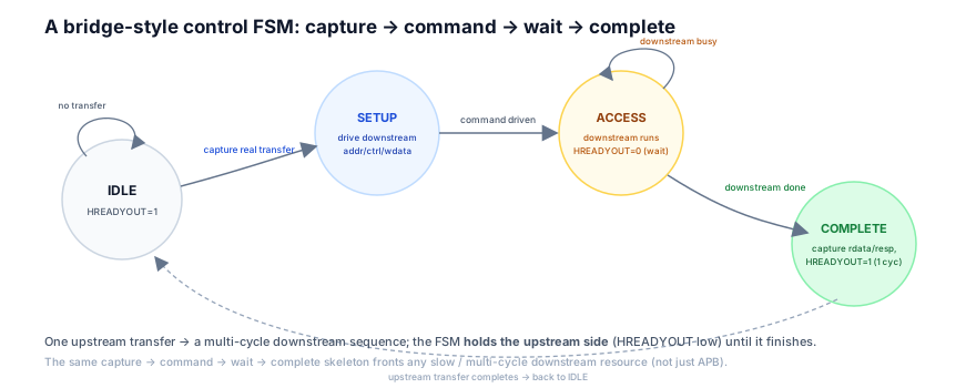
So the bridge FSM is the rate-matching controller between a fast upstream bus and a slow/multi-cycle downstream resource. The simple slaves (16.1–16.3) responded in one cycle (or a few waits) because their resource (registers, SRAM) was directly accessible — their "FSM" collapsed to a capture plus combinational logic. A bridge is different: its resource is another bus transaction (the downstream APB access), which itself takes multiple cycles (a SETUP phase, an ACCESS phase, a wait for the peripheral). So the bridge cannot respond in one cycle — it must run the downstream transaction to completion, holding the upstream master (wait states) the whole time, then complete. That multi-cycle sequencing is what requires a real FSM — IDLE → SETUP → ACCESS → COMPLETE. And crucially, that FSM is built from the blocks you already have: it captures the upstream transfer (16.7), generates HREADYOUT to hold/release (16.4), commits writes / produces reads on completion (16.8/16.9), and maps the downstream response to HRESP (16.6). The bridge FSM is therefore the assembly of the slave building blocks into a multi-cycle controller.
2. Why Does It Exist?
The bridge FSM exists because some slaves front a multi-cycle downstream resource (another bus, a slow peripheral) — so a single upstream transfer expands into a multi-cycle sequence that must be sequenced by a real state machine, holding the upstream master throughout.
The multi-cycle downstream resource is the root: a bridge doesn't hold the data itself (like a register or SRAM) — it forwards the access to a downstream resource (an APB peripheral bus, a slow external interface). That downstream access is itself a multi-cycle transaction — e.g. APB's two-phase SETUP/ACCESS, plus wait cycles for the peripheral. So a single upstream AHB transfer triggers a multi-cycle downstream sequence. So the bridge cannot respond in one cycle: it must drive and track the downstream transaction across cycles, which is what requires states.
The the upstream must be held drives the wait states: since the upstream transfer can't complete until the downstream one does, the bridge must hold the upstream master — insert wait states (HREADYOUT low) — for the entire duration of the downstream sequence. So the FSM's states (SETUP, ACCESS) each drive HREADYOUT low (holding), and only COMPLETE drives it high (releasing). The FSM's job is therefore to manage the holding — coordinating the upstream HREADYOUT with downstream progress.
The assembly of the building blocks is the deeper why: the bridge is where the individual slave outputs (16.4–16.9) must work together across multiple cycles — capture the transfer (16.7), hold/release via HREADYOUT (16.4), commit the write / produce the read on completion (16.8/16.9), map the response (16.6) — all sequenced. A simple slave does these in one cycle (collapsed); a bridge does them across the multi-cycle sequence (an FSM). So the bridge FSM is the integration point that assembles the blocks into a coherent multi-cycle controller. In summary, it exists because: some slaves front a multi-cycle downstream resource (a single upstream transfer expands into a multi-cycle sequence — the why); the upstream master must be held throughout (wait states across SETUP/ACCESS — the rate-matching); and the building blocks must be sequenced together across cycles (the assembly — capture, HREADYOUT, commit, HRESP). The bridge FSM is the multi-cycle slave controller that maps a fast upstream transfer onto a slow downstream transaction, integrating every slave block into a real state machine.
3. Mental Model
Model the bridge FSM as a hotel concierge taking your one request, then carrying out a multi-step errand on your behalf while you wait at the desk. You ask for theater tickets (one upstream transfer). The concierge can't hand them over instantly — they have to call the box office (SETUP), wait while the box office checks availability and processes it (ACCESS, several minutes), and only then hand you the tickets (COMPLETE). Throughout, they keep you politely waiting at the desk ("one moment, please" — HREADYOUT low), and only say "here you are" once the whole errand is done.
A hotel concierge desk (the bridge) between you, the guest (the upstream master) and the outside world (the downstream resource). You make one request — "theater tickets, please" (a single upstream transfer). A simple clerk handling something on-hand (like a room key — a register/SRAM) would hand it over instantly. But the concierge's request isn't on-hand — it requires a multi-step errand with an outside party (the box office — a downstream bus transaction). So the concierge can't respond in one beat. Instead: first they pick up the phone and place the order — "box office, I need two tickets for tonight" (SETUP — driving the downstream command: which show, how many). Then they wait on the line while the box office checks availability and processes the payment — which takes several minutes (ACCESS — the downstream transaction executing, multi-cycle; sometimes the box office says "hold please" — downstream wait states, the self-loop). Throughout all of this, the concierge keeps you politely waiting at the desk — "one moment, please, I'm on it" — not dismissing you, not saying "done" yet (holding the upstream master with HREADYOUT low — wait states). Only when the box office confirms and the tickets are secured does the concierge turn to you and say "here you are" — handing over the tickets (COMPLETE — capturing the downstream result, driving HREADYOUT high for one beat to release you). And if the box office says "sold out" (a downstream error), the concierge relays "I'm sorry, that's not available" (mapping the downstream response to HRESP = ERROR). So the concierge takes one request, runs a multi-step errand with the outside party, holds you waiting the whole time, and completes only when the errand is done — relaying the outcome.
This captures the bridge FSM: your single request = one upstream AHB transfer; the concierge = the bridge control FSM; the on-hand clerk = a simple slave (collapsed, instant); the multi-step errand with the box office = the multi-cycle downstream transaction; placing the order on the phone = SETUP (driving the downstream command); waiting on the line while it processes = ACCESS (the downstream transaction executing, multi-cycle); "hold please" from the box office = downstream wait states (the ACCESS self-loop); keeping you waiting at the desk = holding the upstream master (HREADYOUT low) throughout; "here you are" once done = COMPLETE (HREADYOUT high for one cycle, releasing); relaying "sold out" = mapping the downstream response to HRESP. Take one request, run the multi-step errand, hold the guest waiting, complete and relay only when done.
Watch one upstream transfer span the multi-cycle downstream sequence, holding the master:
One upstream transfer spans the downstream sequence
4 cyclesThe model's lesson: take one request, run the multi-step errand, hold the guest waiting, and complete only when done. In the waveform, the single upstream transfer is stretched across the downstream sequence — HREADYOUT low through SETUP/ACCESS (holding), high only on COMPLETE (releasing).
4. Real Hardware Perspective
In hardware, the bridge is a state register plus next-state/output logic; SETUP/ACCESS drive the downstream interface and hold HREADYOUT low; COMPLETE captures the downstream result and pulses HREADYOUT high; and the whole thing reuses the capture/commit/HRESP logic across the states.
The state register and transitions: the FSM is a state register (state_q ∈ {IDLE, SETUP, ACCESS, COMPLETE}) with next-state logic: IDLE → SETUP on a captured real transfer; SETUP → ACCESS after driving the command; ACCESS → ACCESS while the downstream side is busy (e.g. downstream PREADY low), ACCESS → COMPLETE when the downstream transaction finishes; COMPLETE → IDLE (or → SETUP for a pipelined next transfer). In hardware this is an ordinary Moore/Mealy FSM.
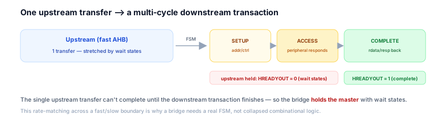
The HREADYOUT held across the states: the HREADYOUT output is a function of the state — low in SETUP and ACCESS (holding the upstream master — the downstream isn't done), high in COMPLETE (releasing — the transfer finishes), high in IDLE (ready for the next). This is exactly the HREADYOUT generation of 16.4 — driven by the FSM state rather than a simple counter. HREADYOUT is therefore the FSM's hold/release output, and the pace is FSM-driven rather than counter-driven.
The reused blocks sequenced across states: the other slave blocks appear within the states. The capture (16.7) happens at IDLE → SETUP (capturing the upstream addr_q/write_q to drive downstream). The write commit (16.8) — here, driving the downstream write data — happens in SETUP/ACCESS (the downstream write executes); the upstream "commit" is the downstream completing. The read production (16.9) — capturing the downstream read data and presenting it on the upstream HRDATA — happens at COMPLETE. The HRESP mapping (16.6) — translating the downstream response (e.g. APB PSLVERR) to the upstream HRESP (OKAY/ERROR, two-cycle) — happens at COMPLETE. So in hardware, the bridge is the slave blocks (16.4–16.9) instantiated and sequenced by the FSM across SETUP/ACCESS/COMPLETE. The FSM is the conductor; the blocks are the players. A bridge is therefore a state machine driving a downstream interface, reusing the capture, HREADYOUT, commit and HRESP logic across its states.
5. System Architecture Perspective
At the system level, the bridge is the rate-matching gateway between a fast high-performance bus and a slow peripheral domain — and its FSM is where the fast/slow boundary is managed, making it both a necessary SoC component and the clearest demonstration that the slave building blocks compose.
The fast/slow gateway: SoCs have a fast bus (AHB — for the CPU, memory, DMA) and a slow peripheral bus (APB — for UARTs, timers, GPIO). The bridge is the gateway between them — it lets the fast bus reach the slow peripherals without slowing the fast bus for everyone (only the bridged accesses pay the slow-peripheral cost). The bridge is therefore the fast-to-slow gateway — a standard SoC component that every microcontroller has.
The boundary management: the bridge's FSM is where the rate mismatch is absorbed. The fast bus expects its protocol (AHB pipelining); the slow bus has its protocol (APB phases); the bridge FSM translates — accepting the fast transfer, holding it (wait states) while running the slow transaction, then completing. So the boundary between the fast and slow domains is managed by the bridge FSM — it's the translation/rate-matching point. The boundary between the fast and slow domains therefore lives in the bridge FSM.
The composition demonstration: the bridge is the proof that the slave building blocks (16.4–16.9) compose into arbitrary slave complexity. A simple slave uses them collapsed (one cycle); a bridge uses them sequenced (multi-cycle FSM); a more complex slave (a cache controller, a DMA-fronting slave) uses them in a richer FSM. The bridge therefore demonstrates the generality of the building-block approach: the same blocks, assembled by an FSM of any complexity. At the system level, the bridge is the rate-matching gateway between fast and slow bus domains (a standard SoC component — the peripheral gateway), its FSM is the domain-boundary manager (absorbing the fast/slow rate mismatch — translating and holding), and it's the clearest demonstration that the slave building blocks compose (the same blocks, sequenced by an FSM, scale to arbitrary slave complexity). The bridge is where the slave RTL culminates: a real multi-cycle controller built entirely from the foundational blocks, managing the most important boundary in the SoC's bus hierarchy. (The detailed bridge architecture — APB protocol, peripheral fan-out, setup/access timing — is a separate subject; here it's the RTL control-FSM capstone.)
6. Engineering Tradeoffs
The bridge FSM embodies the multi-cycle, hold-the-upstream, compose-the-blocks design.
- Real FSM vs collapsed logic. A bridge needs a real FSM (multi-cycle downstream sequencing); a simple slave collapses to combinational logic. Use an FSM only when the slave is genuinely multi-cycle (a bridge, a cache, a complex peripheral).
- Hold with wait states vs buffer/post. Holding the upstream master (wait states) through the downstream access is simplest and correct for a basic bridge; a posted-write buffer (accept the upstream write, complete it immediately, drain to downstream later) improves upstream throughput at the cost of buffering/ordering complexity. Start with holding; add posting if throughput demands.
- Reuse blocks vs bespoke logic. Reusing the capture/
HREADYOUT/commit/HRESPblocks (16.4–16.9) sequenced by the FSM is clean and verified; bespoke per-bridge logic risks re-introducing the subtle bugs. Compose from the verified blocks. - Minimal states vs explicit per-phase states. A minimal FSM (few states) is compact; explicit per-phase states (one per downstream phase) are clearer and easier to verify. Favor clarity for a capstone block.
The throughline: a bridge FSM is the capstone slave controller — a real state machine (IDLE → SETUP → ACCESS → COMPLETE) that maps one upstream transfer onto a multi-cycle downstream transaction, because the bridge fronts a slow/multi-cycle resource (another bus) rather than holding data directly. Throughout SETUP/ACCESS, it holds the upstream master with wait states (HREADYOUT low — chapter 6.2), since the upstream transfer can't finish until the downstream one does; COMPLETE releases it (HREADYOUT high, one cycle) and maps the downstream result to the upstream HRDATA/HRESP. It reuses every block — capture (16.7), HREADYOUT (16.4), write/read commit gated to completion (16.8/16.9), HRESP (16.6) — sequenced by the FSM. It's the fast/slow gateway of the SoC and the proof that the slave blocks compose into arbitrary complexity. (The full bridge protocol is a separate subject.)
7. Industry Example
Trace a CPU write and read through a bridge to a slow peripheral — the rate-matching in action.
A CPU on AHB accesses a UART on a downstream (APB-style) peripheral bus through a bridge.
- The write (CPU → UART config register). The CPU issues one AHB write to the UART's config address. The bridge: IDLE → SETUP captures the upstream transfer and drives the downstream command (the peripheral address, control, and the write data);
HREADYOUTlow (hold the CPU). SETUP → ACCESS: the downstream write executes — the peripheral bus asserts its enable and the UART accepts the write, possibly over several cycles (downstream wait states);HREADYOUTstays low. ACCESS → COMPLETE: the downstream write is accepted (downstreamPREADY); the bridge drivesHREADYOUThigh for one cycle — the CPU's write completes. The CPU was held for the whole downstream sequence. - The read (CPU ← UART status register). The CPU issues one AHB read. IDLE → SETUP: capture, drive the downstream read command;
HREADYOUTlow. SETUP → ACCESS: the downstream read executes — the UART produces its status;HREADYOUTlow until the data is ready. ACCESS → COMPLETE: the downstream read data is valid (downstreamPREADY); the bridge captures it and presents it on the upstreamHRDATA, drivingHREADYOUThigh — the CPU samples the status. Critically, the bridge drivesHREADYOUThigh only when the downstream read data is genuinely ready — not before (which would return garbage). - A downstream error. If the UART signals a downstream error (e.g. APB
PSLVERR), the bridge maps it to the upstreamHRESP = ERROR(the two-cycle ERROR — 16.6) at COMPLETE. The CPU takes a bus fault. - The hold. Throughout both transfers, the CPU is held (
HREADYOUTlow) for the entire downstream sequence — the bridge rate-matches the fast CPU to the slow UART. Only the bridged accesses pay the cost; the rest of the AHB runs full-speed. - The reused blocks. The bridge captured (16.7), generated
HREADYOUT(16.4) from its state, committed the (downstream) write / presented the (downstream) read on completion (16.8/16.9), and mappedHRESP(16.6) — all sequenced by the FSM.
The example shows the bridge FSM rate-matching a fast CPU to a slow peripheral: one upstream transfer stretched across the multi-cycle downstream sequence, the CPU held throughout, completion only on genuine downstream completion (no early release), and the reused slave blocks sequenced by the FSM. (The APB-side protocol detail is developed in the RTL below.)
7b. The Bridge, Written Out
The description above is complete enough to implement directly. What it leaves
implicit is the one interaction that makes a bridge harder than it looks: the
AHB ERROR response takes two cycles, so "COMPLETE drives HREADYOUT high for
one cycle" is true for OKAY and wrong for ERROR. The FSM below separates them.
module ahb_apb_bridge #(
  parameter int AW = 32,
  parameter int DW = 32
) (
  input  logic            HCLK,
  input  logic            HRESETn,

  // ---------------- AHB-Lite subordinate (upstream) ----------------
  input  logic            HSEL,
  input  logic [1:0]      HTRANS,
  input  logic [AW-1:0]   HADDR,
  input  logic            HWRITE,
  input  logic [DW-1:0]   HWDATA,
  input  logic            HREADY,       // GLOBAL ready from the interconnect
  output logic            HREADYOUT,
  output logic [DW-1:0]   HRDATA,
  output logic [1:0]      HRESP,

  // ---------------- APB manager (downstream) -----------------------
  output logic            PSEL,
  output logic            PENABLE,
  output logic            PWRITE,
  output logic [AW-1:0]   PADDR,
  output logic [DW-1:0]   PWDATA,
  input  logic [DW-1:0]   PRDATA,
  input  logic            PREADY,
  input  logic            PSLVERR
);
  localparam logic [1:0] HTRANS_IDLE = 2'b00;
  localparam logic [1:0] RSP_OKAY = 2'b00, RSP_ERROR = 2'b01;

  // ── Address-phase capture, gated on the GLOBAL HREADY.
  //    HWDATA is NOT captured here: in AHB it arrives one cycle later, during
  //    the data phase, so it is sampled separately below.
  logic          sel_q, write_q;
  logic [AW-1:0] addr_q;
  wire           active = HSEL && HTRANS[1];   // NONSEQ or SEQ

  always_ff @(posedge HCLK or negedge HRESETn) begin
    if (!HRESETn) begin
      sel_q <= 1'b0; write_q <= 1'b0; addr_q <= '0;
    end else if (HREADY && HREADYOUT) begin
      // Only accept a new address phase when THIS slave is also releasing.
      // While the bridge is stretching, the master holds its address phase,
      // so re-capturing would be harmless but re-arming the FSM would not.
      sel_q <= active; write_q <= HWRITE; addr_q <= HADDR;
    end
  end

  // ── The FSM. B_ERR1/B_ERR2 exist solely because AHB's ERROR response is a
  //    two-cycle sequence; the OKAY path completes straight out of B_ACCESS.
  typedef enum logic [2:0] {
    B_IDLE, B_SETUP, B_ACCESS, B_ERR1, B_ERR2
  } state_e;
  state_e state, next;

  // APB write data is the AHB write data of the cycle after the address phase.
  logic [DW-1:0] wdata_q, prdata_q;
  always_ff @(posedge HCLK) begin
    if (state == B_IDLE && sel_q && write_q) wdata_q  <= HWDATA;
    if (state == B_ACCESS && PREADY)         prdata_q <= PRDATA;
  end

  always_comb begin
    next = state;
    unique case (state)
      // A captured transfer starts the downstream access.
      B_IDLE  : if (sel_q) next = B_SETUP;
      // APB SETUP is exactly one cycle: PSEL high, PENABLE low.
      B_SETUP : next = B_ACCESS;
      // APB ACCESS holds PSEL and PENABLE until PREADY. The transfer occurs
      // on the cycle where PSEL && PENABLE && PREADY are all true, and
      // PSLVERR is only meaningful in that same cycle.
      B_ACCESS: if (PREADY) next = PSLVERR ? B_ERR1
                                           : (sel_q ? B_SETUP : B_IDLE);
      B_ERR1  : next = B_ERR2;
      B_ERR2  : next = sel_q ? B_SETUP : B_IDLE;
    endcase
  end

  always_ff @(posedge HCLK or negedge HRESETn)
    if (!HRESETn) state <= B_IDLE; else state <= next;

  // ── APB outputs.
  //    PENABLE must be low for the whole SETUP cycle and high through ACCESS.
  //    Holding it high into a back-to-back transfer is an APB violation, which
  //    is why B_ACCESS returns through B_SETUP rather than looping directly.
  assign PSEL    = (state == B_SETUP) || (state == B_ACCESS);
  assign PENABLE = (state == B_ACCESS);
  assign PWRITE  = write_q;
  assign PADDR   = addr_q;
  assign PWDATA  = wdata_q;

  // ── AHB outputs.
  //    HREADYOUT is high in IDLE (nothing in flight) and on the completing
  //    cycle of an OKAY transfer. It is LOW during the first ERROR cycle and
  //    high on the second - that is the two-cycle ERROR sequence.
  assign HREADYOUT = (state == B_IDLE)
                  || (state == B_ACCESS && PREADY && !PSLVERR)
                  || (state == B_ERR2);

  assign HRESP  = (state == B_ERR1 || state == B_ERR2) ? RSP_ERROR : RSP_OKAY;

  // Read data is presented on the completing cycle, taken combinationally from
  // PRDATA (which APB guarantees valid when PREADY is high). prdata_q exists
  // for designs that prefer to register it and add a completion cycle.
  assign HRDATA = PRDATA;
endmodule
Three points in that file are the ones a prose description leaves out.
HWDATA is not captured with the address. AHB's write data arrives one cycle
after its address phase, so a bridge that latches HWDATA alongside HADDR
captures the previous transfer's data. The capture block takes the address
phase; a separate register takes the data phase.
PENABLE must drop between transfers. APB defines the access phase as one
PENABLE-high region terminated by PREADY, so back-to-back transfers go
ACCESS → SETUP → ACCESS, not ACCESS → ACCESS. The FSM routes through B_SETUP
for exactly this reason; looping in B_ACCESS would save a cycle and violate the
protocol.
ERROR costs a state pair. On PSLVERR the bridge cannot simply raise
HREADYOUT with HRESP = ERROR. AHB requires ERROR to span two cycles —
HREADYOUT low with HRESP asserted, then HREADYOUT high with HRESP still
asserted — so the master gets a cycle in which to cancel the address phase it has
already issued. B_ERR1 and B_ERR2 are that sequence.
Checking it
module ahb_apb_bridge_sva (
  input logic HCLK, HRESETn,
  input logic HREADYOUT, input logic [1:0] HRESP,
  input logic PSEL, PENABLE, PREADY, PSLVERR, PWRITE,
  input logic [31:0] PADDR, PWDATA
);
  localparam logic [1:0] RSP_ERROR = 2'b01;

  // --- APB side ---
  // SETUP lasts exactly one cycle: PSEL without PENABLE is always followed by
  // PSEL with PENABLE.
  a_setup_one_cycle: assert property (@(posedge HCLK) disable iff (!HRESETn)
    (PSEL && !PENABLE) |=> (PSEL && PENABLE));

  // Once in ACCESS, PSEL/PENABLE hold until PREADY. No aborting.
  a_access_holds: assert property (@(posedge HCLK) disable iff (!HRESETn)
    (PSEL && PENABLE && !PREADY) |=> (PSEL && PENABLE));

  // Address and write data are stable for the whole transfer.
  a_apb_stable: assert property (@(posedge HCLK) disable iff (!HRESETn)
    (PSEL && !(PENABLE && PREADY)) |=>
      $stable(PADDR) && $stable(PWRITE) && $stable(PWDATA));

  // PENABLE must drop after a completed access - no ACCESS-to-ACCESS.
  a_penable_drops: assert property (@(posedge HCLK) disable iff (!HRESETn)
    (PSEL && PENABLE && PREADY) |=> !PENABLE);

  // --- AHB side ---
  // The two-cycle ERROR: the first ERROR cycle has HREADYOUT low, and the
  // next cycle must still assert ERROR, now with HREADYOUT high.
  a_error_two_cycle: assert property (@(posedge HCLK) disable iff (!HRESETn)
    (HRESP == RSP_ERROR && !HREADYOUT) |=> (HRESP == RSP_ERROR && HREADYOUT));

  // An ERROR never appears as a single completing cycle out of nowhere.
  a_error_not_one_cycle: assert property (@(posedge HCLK) disable iff (!HRESETn)
    (HRESP == RSP_ERROR && HREADYOUT) |->
      $past(HRESP == RSP_ERROR && !HREADYOUT));

  // Coverage: without these, a green run cannot distinguish "error path
  // correct" from "error path never taken".
  c_error_seen: cover property (@(posedge HCLK) disable iff (!HRESETn)
    PSEL && PENABLE && PREADY && PSLVERR);
  c_wait_seen:  cover property (@(posedge HCLK) disable iff (!HRESETn)
    PSEL && PENABLE && !PREADY);
endmoduleA bridge reported peripheral errors that the CPU never took a fault on
ONE-CYCLE-ERRORAccesses to an unmapped peripheral register behaved inconsistently. The APB
peripheral correctly asserted PSLVERR, the bridge correctly drove
HRESP = ERROR, and the CPU sometimes took a bus fault and sometimes did not —
with the outcome depending on what instruction followed the faulting access. A
faulting load followed by an unrelated nop faulted; the same load followed by
another load to a different peripheral often did not, and instead corrupted the
second load's result.
// The error path completed in a single cycle, like the OKAY path.
assign HREADYOUT = (state == B_IDLE)
                || (state == B_ACCESS && PREADY);          // <-- error included

assign HRESP = (state == B_ACCESS && PREADY && PSLVERR) ? RSP_ERROR : RSP_OKAY;A waveform of a faulting access showed HRESP asserted for exactly one cycle,
in the same cycle HREADYOUT went high. The AHB master's own trace showed it had
already driven the next transfer's address phase during that cycle — which is
normal, because AHB is pipelined and the address phase of transfer N+1 overlaps
the data phase of transfer N.
That overlap is the entire mechanism. The master issues the next address phase speculatively; the ERROR response is its signal to cancel it. Delivering the ERROR and the completion in the same cycle gives the master no cycle in which to act, so whether it cancels depends on internal implementation details — which is exactly the instruction-dependent behaviour that was observed.
AHB defines the ERROR response as a two-cycle sequence: HRESP = ERROR with
HREADYOUT low, then HRESP = ERROR with HREADYOUT high. The first cycle is
not a formality — it exists so the master can see the error while its next
address phase is still uncommitted and drive HTRANS to IDLE to cancel it. The
bridge collapsed the two cycles into one, so the error and the completion arrived
together and the master's speculatively-issued next transfer proceeded anyway.
The reason this survived block-level testing is the usual one for pipeline bugs: a testbench that issues one transfer at a time, waiting for each to complete before starting the next, never has a speculative address phase in flight. There is nothing to cancel, so a one-cycle ERROR and a two-cycle ERROR are indistinguishable. Only back-to-back traffic separates them, and only when the first of the pair errors.
// Split the error completion into the two cycles the protocol requires.
B_ACCESS: if (PREADY) next = PSLVERR ? B_ERR1 : (sel_q ? B_SETUP : B_IDLE);
B_ERR1  : next = B_ERR2;
B_ERR2  : next = sel_q ? B_SETUP : B_IDLE;

assign HREADYOUT = (state == B_IDLE)
                || (state == B_ACCESS && PREADY && !PSLVERR)  // OKAY: 1 cycle
                || (state == B_ERR2);                          // ERROR: 2nd cycle

assign HRESP = (state == B_ERR1 || state == B_ERR2) ? RSP_ERROR : RSP_OKAY;
The test that separates the two is a back-to-back pair in which the first access errors: issue a faulting transfer immediately followed by a second transfer to a different address, and check that the second one does not complete. Against the old RTL the second transfer proceeds and returns data; against the new RTL the master sees the error with a cycle to spare and cancels it.
The assertion is the durable form, because it holds regardless of what the stimulus happens to do:
a_error_two_cycle: assert property (@(posedge HCLK) disable iff (!HRESETn)
  (HRESP == RSP_ERROR && !HREADYOUT) |=> (HRESP == RSP_ERROR && HREADYOUT));
a_error_not_one_cycle: assert property (@(posedge HCLK) disable iff (!HRESETn)
  (HRESP == RSP_ERROR && HREADYOUT) |-> $past(HRESP == RSP_ERROR && !HREADYOUT));
Pair them with c_error_seen from the checker above. A two-cycle-ERROR assertion
in a regression that never generates an error is vacuously true, and a bridge
whose error path has never been exercised is a bridge whose error path is
unverified — see error response
and the two-cycle ERROR response for the response rules in full.
8. Common Mistakes
9. Interview Insight
The bridge FSM is a senior RTL interview topic — the multi-cycle-needs-an-FSM insight, the hold-the-upstream discipline, and the reuses-every-block framing are the signals.
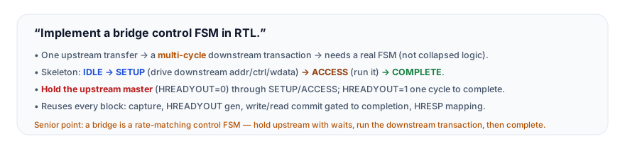
The answer that lands gives the multi-cycle insight and the hold discipline: "A bridge is the most complex slave because, unlike a simple slave or a memory that holds the data directly, a bridge fronts a downstream resource — another bus, like APB — and one upstream transfer expands into a multi-cycle downstream transaction. So it can't collapse to combinational logic; it needs a real control FSM. The skeleton is: from idle, capture a real upstream transfer and go to a setup state that drives the downstream command — the address, control, and for a write the write data. Then an access state where the downstream transaction actually executes, which takes one or more cycles. Then a complete state that captures the downstream read data or response and finishes the upstream transfer. The critical discipline is that throughout setup and access, you hold the upstream master by driving HREADYOUT low — inserting wait states — because the single upstream transfer can't complete until the downstream transaction finishes. You only drive HREADYOUT high, completing the upstream transfer, when the downstream side genuinely completes. Releasing early is the classic bug: for a read, you'd return garbage because the downstream data isn't back yet; for a write, you'd break ordering by telling the master it's done before downstream accepted it. And the elegant part is that the bridge reuses every building block — the address capture, the HREADYOUT generation, the write and read commit gated to completion, the HRESP mapping from the downstream response — all sequenced by the FSM. The FSM is the conductor; the blocks are the players. So a bridge is really a rate-matching control FSM between a fast and a slow bus." The multi-cycle-needs-an-FSM insight, the hold-the-upstream discipline (and the early-release bug), and the reuses-every-block framing are the senior signals.
10. Practice Challenge
Build and reason from the bridge FSM.
- Why an FSM. Explain why a bridge needs a real control FSM while a simple slave/memory doesn't (the multi-cycle downstream expansion).
- The states. Describe the
IDLE → SETUP → ACCESS → COMPLETEskeleton and what happens in each state. - Read the waveform. From Figure 2, explain how one upstream transfer spans the downstream sequence, and how
HREADYOUTholds then releases. - Hold discipline. Explain why the bridge holds the upstream master for the entire downstream sequence, and the early-release bug (reads and writes).
- Reuse. Explain how the bridge reuses the capture,
HREADYOUT, commit, andHRESPblocks, sequenced by the FSM.
10b. Where This Is Specified
- Arm AMBA 5 AHB Protocol Specification (ARM IHI 0033). The address-phase/data-phase pipeline and the requirement that write data appears one cycle after its address phase; the
HREADY/HREADYOUTdistinction; and the two-cycle ERROR response —HRESPasserted withHREADYOUTlow, then asserted again withHREADYOUThigh — that exists so a manager can cancel an address phase it has already issued. - Arm AMBA APB Protocol Specification (ARM IHI 0024). The IDLE → SETUP → ACCESS state model,
PSELasserted in SETUP withPENABLElow for exactly one cycle,PENABLEasserted through ACCESS, the transfer completing only whenPSEL && PENABLE && PREADY, andPSLVERRbeing meaningful only in that completing cycle. - IEEE 1800-2023 §16 — Assertions. The concurrent properties and
cover propertyconstructs used by the protocol checker on both interfaces.
11. Key Takeaways
- A bridge needs a real control FSM — one upstream transfer expands into a multi-cycle downstream transaction, which can't collapse to combinational logic (unlike 16.1–16.3).
- The skeleton is
IDLE → SETUP → ACCESS → COMPLETE— capture the upstream transfer, drive the downstream command, run the downstream transaction (multi-cycle), then complete. - Hold the upstream master throughout SETUP/ACCESS (
HREADYOUTlow — wait states), since the upstream transfer can't finish until downstream does; release (HREADYOUThigh, one cycle) only on COMPLETE. - Complete only on genuine downstream completion — releasing early returns garbage reads (data not back) and breaks ordering/error-reporting on writes. The multi-cycle generalization of the
HREADYOUT/commit discipline (16.3/16.4/16.8). - It reuses every slave block — capture (16.7),
HREADYOUT(16.4), write/read commit gated to completion (16.8/16.9),HRESPmapping (16.6) — sequenced by the FSM (the conductor; the blocks are the players). - It's the fast/slow gateway of the SoC and the proof the slave blocks compose into arbitrary complexity. (The full AHB-to-APB bridge protocol is a separate subject.)
12. What Comes Next
You now can build the capstone multi-cycle slave controller. The final chapter of this module packages the building blocks for reuse:
- Reusable AHB RTL Templates (next) — drop-in, parameterised AHB RTL building blocks (capture, slave, memory, bridge skeletons) you can instantiate and configure.
To revisit the blocks the bridge sequences, see Address / Control Capture, HREADYOUT Generation, Write FSM, and HRESP Generation; for crossing clock domains in a bridge, see CDC Bridges.