AMBA AHB · Module 11
The Address Map
The SoC address map — the system-level table that assigns address ranges (base + size) to slaves and is the contract the AHB decoder enforces in hardware; how disjoint, power-of-two-aligned regions drive the decode, why gaps need a default slave, and why the map must match the linker and software.
Chapters 11.1–11.3 covered the decode mechanism (decoder → one-hot HSEL → default slave). This chapter steps up to the spec behind it: the address map. An address map is the system-level table that assigns each slave an address region (a base address and a size), defining where everything lives in the address space. It's the contract the decoder enforces: each region becomes one comparator in the decoder, and the map's structure (disjoint regions, power-of-two alignment, gaps covered by a default) is exactly what makes the decode correct and cheap. The map is also a cross-domain contract — it must match the linker script (where code/data are placed), the software headers (peripheral base addresses), and the hardware decoder, or the system breaks. This chapter covers what an address map is, how it drives the decoder, the alignment/disjointness rules, and the hardware/software consistency it demands.
1. What Is It?
An address map is a system-level assignment of address ranges to slaves. Each entry is a region:
- A base address — where the region starts.
- A size — how large the region is (so it spans
[base, base+size)). - The slave that owns it (RAM, flash, a peripheral, etc.).

So the address map is the floor plan of the address space: it says "RAM lives here, this peripheral lives there, this range is unused." It's typically drawn as a vertical map (low address at the bottom, high at the top) with each slave's region marked by its base and size, and the gaps between them. The map is a system-level artifact — defined by the SoC architect, documented in the technical reference manual, and shared across hardware and software. It's the single source of truth for where everything is. The decoder (chapters 11.1–11.2) is the hardware that enforces this map; the map itself is the specification.
2. Why Does It Exist?
The address map exists because a system with multiple slaves sharing one address space needs a single, agreed definition of which slave owns which addresses — so that the decoder can route correctly, software can find each peripheral, and the whole system has one source of truth for the address space.
The shared-address-space problem is the root cause: in an SoC, the master(s) issue addresses into a single address space (e.g. 32 bits = 4 GB), and many slaves (memories, peripherals) live in that space. For any address, exactly one slave should own it. So there must be a definition of which slave owns which range — that definition is the address map. Without it, there'd be no agreed answer to "what's at address X?" — the decoder wouldn't know what to select, and software wouldn't know where to find a peripheral. So the address map exists to define ownership of the shared address space — the prerequisite for both hardware routing and software access. So the map is the foundational agreement that makes the shared address space usable.
The reason the map must be a single source of truth is consistency across domains: the address map is used by multiple parts of the system. The hardware decoder uses it to route transfers. The linker script uses it to place code and data at the right addresses (e.g. code in ROM at 0x0000_0000, stack in RAM). The software/firmware uses it to access peripherals (a driver writes to the UART at its base address). If these disagree — say the decoder maps the UART at 0x4000_0000 but the software header says 0x4000_1000 — the software writes to the wrong place (or to a gap → bus fault). So the map must be consistent across hardware, linker, and software. Making it a single source of truth (one authoritative definition all three derive from) prevents these mismatches. So the map exists as a single source of truth to keep hardware and software in agreement about the address space. So the address map exists to define ownership of the shared address space and to be the single consistent contract across the decoder, linker, and software.
The reason regions are disjoint and (usually) power-of-two aligned is correct, cheap decoding: disjoint regions ensure the decode is unambiguous (each address → exactly one slave → one-hot HSEL, no contention). Power-of-two alignment and sizing make the decode a simple comparison of upper address bits (chapter 11.1) — a region [base, base+size) with power-of-two size and base aligned to size is exactly the set of addresses whose top bits equal base's top bits, so the decode is HADDR[31:k] == base[31:k] — cheap. Non-power-of-two or unaligned regions need range comparisons (base <= HADDR < base+size) — costlier (chapter 11.6). So the map is structured (disjoint, aligned) to make the decoder correct and cheap. So the address map exists, structured this way, to define the shared address space as a single consistent contract that the decoder can enforce correctly and cheaply.
3. Mental Model
Model the address map as the master directory of a large office building — it assigns every suite a number range on each floor (Suites 100–199 to Accounting, 200–299 to Engineering), and that one directory is what the lobby guard uses to route visitors, what the mail carrier uses to deliver, and what the printed business cards reference; if the directory, the guard's list, and the business cards ever disagree, visitors and mail end up at the wrong suite.
A large office building has a master directory (the address map) assigning each department a range of suite numbers (a region: base + size). The lobby guard (the decoder) uses this directory to route each visitor to the right suite — reading the suite number on the visitor's badge and sending them to the department that owns that range. But the directory isn't only the guard's tool: the mail carrier (the linker, placing things) uses it to deliver mail to the right department, and the business cards and letterhead (software headers) print the suite numbers so people know where to send things. Crucially, all of these derive from the one master directory — if the guard's routing list, the mail carrier's manifest, and the printed business cards ever disagree about where Engineering is, visitors get sent to the wrong floor and mail is misdelivered. And suites are assigned in clean blocks (100–199, not 137–284) so routing is simple ("first digit = department"), and any unassigned suite numbers route to a lost-and-found desk (the default slave) rather than nowhere. So one master directory, used consistently by the guard, the carrier, and the cards, with clean blocks and a lost-and-found.
This captures the address map: the master directory = the address map; suite-number ranges = regions (base + size); the guard routing = the decoder; the mail carrier = the linker placing code/data; the business cards = software headers/base addresses; all deriving from one directory = single source of truth; clean suite blocks = power-of-two-aligned regions (simple decode); the lost-and-found = the default slave. One consistent directory drives routing, placement, and reference — disjoint, clean blocks, with a fallback.
Watch the map drive selection as HADDR sweeps across regions:
The address map drives slave selection
5 cyclesThe model's lesson: one master directory routes everyone consistently, in clean blocks, with a lost-and-found. In the waveform, each address selects the slave the map assigns — and a gap address routes to the default slave.
4. Real Hardware Perspective
In hardware, the address map is realized as the decoder's comparator constants, and its structure (alignment, sizing) directly determines how many address bits the decoder compares and how cheap the logic is.
The map → comparator translation is the realization: each region in the map becomes a comparison in the decoder. For a power-of-two region of size 2^n aligned to 2^n, the decoder compares HADDR[31:n] against the region's base bits base[31:n] — an equality check on the upper (32-n) bits. So a 64 KB region (2^16) is selected by comparing HADDR[31:16] against the base's top 16 bits. The map's base addresses and sizes thus become the constants and bit-widths in the decoder's comparators. So in hardware, the map is literally the set of decoder comparator constants — change the map, change the constants.
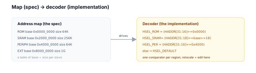
The alignment dictates decode cost: a region that's power-of-two sized and aligned to its size decodes with a single upper-bits equality (cheap). A region that's unaligned or non-power-of-two-sized needs a range comparison (base <= HADDR < base+size) — two magnitude comparators, costlier and slower (chapter 11.6 covers this). So the map's alignment choices directly trade off against decoder area and timing. This is why SoC address maps overwhelmingly use power-of-two, aligned regions — it keeps the decode cheap. So in hardware, the map's structure is chosen partly for the decoder's benefit. So the hardware perspective is: the map becomes comparator constants, and aligned power-of-two regions keep those comparators cheap (upper-bits equality), which is why maps are structured that way.
The hierarchical decode is a common hardware pattern the map reflects: a top-level decoder selects a coarse region (e.g. "the peripheral block at 0x4000_0000"), and a sub-decoder within that block selects the specific peripheral (UART vs timer vs GPIO) using lower address bits. So the map is hierarchical: coarse regions at the top, fine sub-regions within. This keeps each decoder small (few comparisons) and matches the physical hierarchy (a peripheral bus bridged off the main bus). So in hardware, the address map is often realized as a hierarchy of decoders — top-level for coarse regions, sub-decoders for the peripherals within a block. So the map drives a (possibly hierarchical) set of decoders, with alignment chosen to keep each comparison cheap.
5. System Architecture Perspective
At the system level, the address map is one of the foundational architectural artifacts of an SoC — it's co-designed with the decoder, it's the contract binding hardware and software, and getting it right (or wrong) ripples through the entire system.
The co-design with the decoder is the first system point: the address map and the decoder are two views of the same decision. The architect defines the map (the spec); the RTL implements the decoder (the enforcement). They're co-designed: the map's structure (alignment, sizing) is chosen with the decoder's cost in mind, and the decoder is generated from (or verified against) the map. Many design flows generate the decoder RTL directly from a machine-readable map (a register/memory-map description), guaranteeing they match. So at the system level, the map and decoder are a co-designed pair — the map is authored, the decoder is derived or checked against it. This is why address-map description formats (IP-XACT, SystemRDL, vendor-specific) exist: to be the single source from which decoder RTL, documentation, and software headers are all generated.
The hardware/software contract is the second, critical system point: the address map is the interface between the hardware and the software. Software accesses peripherals and memory by address, so it must know the map: a driver writes the UART's control register at the UART base + offset; the linker places the program's code, data, and stack at the right addresses; the boot code knows where ROM and RAM are. All of this depends on the map. If the hardware decoder and the software's idea of the map diverge, the software accesses the wrong addresses — writing to a gap (bus fault), to the wrong peripheral (corruption), or reading garbage. So the map must be consistent across the decoder, the linker script, and the software headers. This is enforced by deriving all of them from one source (the map description) — a key SoC discipline. So at the system level, the map is the hardware/software contract, and its consistency across domains is a correctness requirement.
The architectural ripple is the third point: the address map decisions ripple widely. Alignment and sizing affect decoder cost (system 4). Region placement affects software (linker scripts, MMU/MPU region setup, cache attributes per region). Reserving space for future expansion (leaving gaps for more memory/peripherals) is an architectural foresight baked into the map. Security/protection often layers on the map (which regions are privileged, which are non-secure — TrustZone-style). So the address map is a high-leverage architectural artifact: it touches decoding, software, memory protection, security, and future-proofing. A well-designed map (clean alignment, room to grow, sensible grouping) makes the whole system cleaner; a poorly-designed one (awkward alignment, no room, scattered peripherals) causes friction everywhere. So at the system level, the address map is a foundational, high-leverage artifact — co-designed with the decoder, the binding hardware/software contract, and a decision that ripples through decoding cost, software, protection, and future expansion. It deserves careful, early architectural attention.
6. Engineering Tradeoffs
The address map embodies the structured-address-space design.
- Power-of-two aligned vs arbitrary regions. Power-of-two, aligned regions decode with a cheap upper-bits equality and give clean offsets, at the cost of sometimes over-allocating address space (a 40 KB RAM in a 64 KB region wastes 24 KB of address space — cheap, since address space is plentiful). Arbitrary regions pack tightly but need costly range decode. Maps overwhelmingly use power-of-two aligned regions.
- Coarse (hierarchical) vs flat decode. A hierarchical map (coarse top-level regions, sub-decoded blocks) keeps each decoder small and matches physical structure, at the cost of decode hierarchy. A flat map (every slave decoded at the top) is simpler conceptually but makes the top decoder large. Larger systems use hierarchy.
- Tight packing vs room to grow. Packing regions tightly maximizes usable space but leaves no room for expansion; leaving gaps (reserved ranges) wastes address space but allows adding memory/peripherals later without remapping. Most maps reserve generous gaps (address space is cheap in a 32/64-bit space).
- Single source vs hand-maintained copies. Generating decoder RTL, linker scripts, and software headers from one map description guarantees consistency, at the cost of tooling. Hand-maintaining separate copies is simpler initially but drifts (hardware/software mismatch bugs). Mature flows use a single source.
The throughline: the address map is the system-level table assigning each slave a region (base + size); it's the contract the decoder enforces (each region → one comparator), structured to be disjoint (one-hot HSEL), power-of-two aligned (cheap upper-bits decode), and total (gaps → default slave). It's co-designed with the decoder and is the binding contract across hardware, linker, and software — so it must be a single source of truth. It's a high-leverage architectural artifact touching decode cost, software, protection, and expansion.
7. Industry Example
Trace an address map through hardware and software.
An MCU has the map from Figure 1: ROM at 0x0000_0000, SRAM at 0x2000_0000, peripherals at 0x4000_0000, external memory at 0x8000_0000.
- The map drives the decoder. The SoC's decoder is generated from the map: it compares HADDR's upper bits to select ROM, SRAM, the peripheral block, or external memory, defaulting to the default slave for gaps. The peripheral block has a sub-decoder selecting the UART (
0x4000_0000), timer (0x4000_1000), GPIO (0x4000_2000). - The map drives the linker. The firmware's linker script places
.text(code) in ROM at0x0000_0000,.data/.bssin SRAM at0x2000_0000, and the stack at the top of SRAM. These addresses come straight from the map. So the program is laid out to match where the memories actually are. - The map drives software. The firmware's headers define
UART_BASE = 0x4000_0000,TIMER_BASE = 0x4000_1000, etc. A UART driver writes its control register atUART_BASE + CTRL_OFFSET. These base addresses come from the map. - Consistency check. All three — decoder, linker script, software headers — are generated from one machine-readable map description (a SystemRDL/IP-XACT file). So they're guaranteed consistent: the address the software writes is the address the decoder routes to the right peripheral, and the linker places code where the decoder expects ROM.
- A divergence bug (counter-example). Suppose someone manually edits the software header to
TIMER_BASE = 0x4000_8000(a typo, landing in a gap). The timer driver's accesses now go to the gap → default slave → bus fault. The timer appears "dead." The bug isn't in the driver logic — it's the header/map mismatch. With a single-source-generated header, this couldn't happen.
The example shows the map as the hub: it drives the decoder (routing), the linker (placement), and the software (access), and consistency across these is what makes the system work. Generating all three from one map description is the discipline that prevents divergence bugs. The map is the contract that binds hardware and software into a coherent address space.
8. Common Mistakes
9. Interview Insight
The address map is a system-design interview topic — the map-as-contract, the alignment-for-cheap-decode, and the hardware/software consistency are the signals.
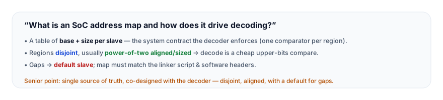
The answer that lands frames the map as a system contract: "The address map is the system-level table that assigns each slave a region — a base address and a size — defining where everything lives in the address space. It's the contract the decoder enforces: each region becomes a comparator that asserts that slave's HSEL when HADDR falls in the region. The map is structured for correctness and cost: regions are disjoint, so the decode is one-hot (no two slaves selected); they're usually power-of-two aligned and sized, so the decode is a cheap comparison of the upper address bits rather than a range check; and gaps are covered by the default slave, so the decode is total. Critically, the map isn't just hardware — it's the contract binding hardware and software: the decoder routes by it, the linker places code and data by it, and the software accesses peripherals by their base addresses from it. So all three must be consistent — ideally generated from one machine-readable map description — or you get silent corruption bugs where software writes to the wrong place. The map is a foundational architectural artifact, co-designed with the decoder." The map-as-contract, the alignment-for-cheap-decode, and the hardware/software consistency are the senior signals.
10. Practice Challenge
Reason from the address map.
- Define it. Describe what an address map is and the three things it drives (decoder, linker, software).
- Alignment. Explain why regions are usually power-of-two aligned and what it does to the decode logic.
- Read the waveform. From Figure 2, explain how the map routes each HADDR value, including the gap.
- Consistency. Explain what goes wrong if the software's idea of the map diverges from the hardware decoder, and how single-source generation prevents it.
- Hierarchy. Explain hierarchical decoding and why a peripheral block is sub-decoded.
11. Key Takeaways
- The address map is a system-level table assigning each slave a region (base + size) — defining where everything lives in the address space.
- It's the contract the decoder enforces — each region becomes one comparator that asserts that slave's HSEL; the map is the spec, the decoder is the implementation.
- It's structured for correctness and cost — disjoint regions (one-hot HSEL), power-of-two aligned/sized (cheap upper-bits decode, not range checks), and gaps covered by the default slave (total decode).
- It binds hardware and software — the decoder, the linker script, and the software's peripheral base addresses all depend on it, so all three must be consistent (ideally generated from one source) or silent corruption bugs result.
- It's often hierarchical — coarse top-level regions, sub-decoded blocks (e.g. a peripheral block) — keeping each decoder small and matching the physical bus structure.
- It's a high-leverage architectural artifact — touching decode cost, software, MMU/MPU/security regions, and future expansion; it deserves careful early design.
12. What Comes Next
You now understand the address map — the system contract that drives the decoder and binds hardware to software. The next chapters cover what happens at the edges of the map:
- Illegal Address Behavior (next) — what happens on access to an unmapped region, and how the system (master/CPU) handles the resulting error.
- Sparse Memory Maps — decoding for sparse, non-power-of-two regions (range decode, partial decode, aliasing).
- Peripheral Selection — how peripherals are selected and addressed on the bus.
To revisit the decode and default slave this builds on, see Address Decoding and The Default Slave.