AMBA APB · Module 4
Multi-Cycle Transfers
How PREADY held low stretches a transfer across multiple cycles — one and multi-wait timing, the signals held stable through the wait, and why a wait stretches access without restarting setup.
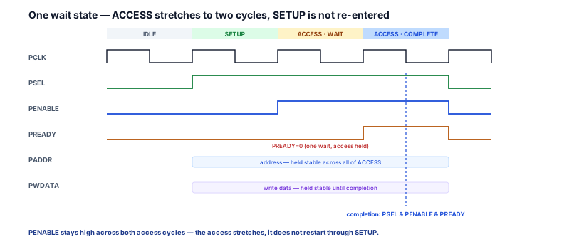
So far you have read APB transfers that finish in their first access cycle. Real subordinates are slower than that, and the protocol's answer is to stretch one access across several cycles by holding PREADY low — a multi-cycle transfer. The crucial discipline is that this is one access getting longer, not several accesses or a re-run: the setup phase is entered exactly once, the access phase absorbs every wait, and the access-defining signals stay frozen until the one completion edge. The single idea to carry: a wait state stretches the access — it never restarts the setup, and nothing on the bus may change until PREADY finally goes high.
1. What problem is being solved?
The problem is letting a subordinate take as long as it needs for one access without changing the shape, the addressing, or the completion rule of the transfer.
A configuration register answers in a single cycle; a register in a slower clock domain, or a bridge to another bus, may need three, five, or ten. The manager cannot know the latency in advance and must not have to. APB's solution is to make the access phase elastic in time while keeping everything else identical:
- The transfer still starts with one SETUP cycle that presents the address and asserts
PSEL. - The access phase then stretches — the subordinate holds
PREADYlow for as many cycles as it needs, and each such cycle is a wait state that holds the access in place. - The transfer still completes on exactly one cycle: the first access cycle where
PREADYis high.
A multi-cycle transfer is therefore not a different kind of transfer. It is the ordinary transfer with extra cycles inserted into one phase — the access phase — and nothing else moved.
2. Why the previous model is not enough
The single-cycle transfer gave you the clean two-phase picture: one SETUP, one ACCESS, done. That is correct but incomplete, because it quietly assumes the subordinate is always ready. The moment a subordinate is not ready, three questions appear that the single-cycle view cannot answer:
- Which phase grows — and does the transfer restart? It is tempting to imagine the FSM bouncing back to SETUP, or re-presenting the address, to "try again." It does neither. The access phase grows in place; SETUP is entered once and never re-visited.
PENABLEstays high across every wait cycle — it does not toggle back down. - What is the manager allowed to do while it waits? Nothing that touches the access.
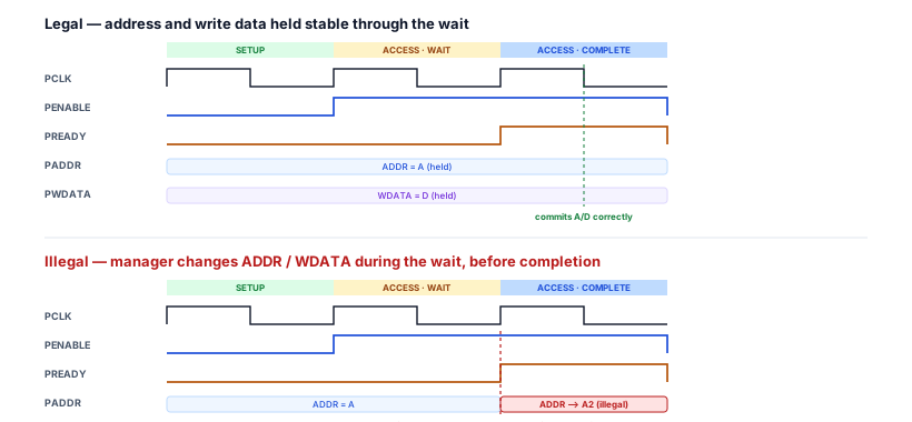
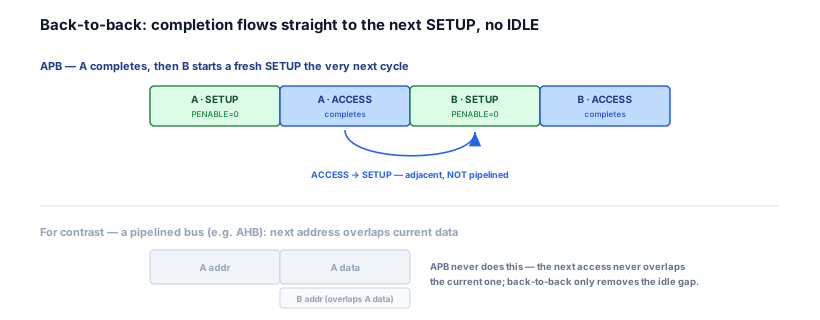
PADDR,PWRITE,PWDATA, and the selectedPSELmust stay byte-for-byte stable through every wait until completion. The single-cycle model never had a cycle in which the manager could change something mid-access, so it never stated the rule. - Does stretching transfers buy throughput? No. Even when transfers run back-to-back with no idle gap, each access is still performed alone — the next one never overlaps the current one. The single-cycle view, by only ever showing one transfer, hides the fact that adjacency is not pipelining.
So the model to add is not a new phase or a new signal. It is the behaviour of the existing access phase when it lasts more than one cycle — what stretches, what is frozen, and what is still illegal.
3. Mental model
The model: a wait state is a pause button held down on the access — the frame freezes, time passes, and nothing on the bus moves until the button is released.
Picture the transfer as a single frame of film: address on PADDR, write data on PWDATA, PSEL and PENABLE high, the subordinate looking at all of it. While PREADY is low, the manager is holding the pause button: the frame is frozen, the clock keeps ticking, but not a single value changes. The instant the subordinate releases the button — drives PREADY high — the frame advances: the write lands, the read data is valid, and the transfer is over. One frozen frame, however many cycles long, is one access.
Three refinements make the model precise:
- The pause lives in ACCESS, not SETUP. Wait states are inserted only after
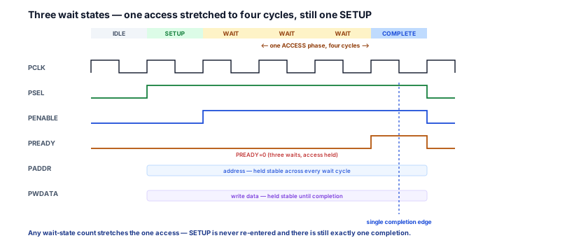
PENABLEhas risen. SETUP is a single cycle that happens once; you never pause it and never re-enter it. A three-wait transfer is one SETUP cycle followed by four access cycles, not four whole transfers. - A frozen frame must stay frozen. Because the subordinate is allowed to act on the bus on the cycle it finally raises
PREADY, every input it might act on — address, write data, write/read direction, select — must be unchanged from the cycle the access began. Changing any of them mid-pause shows the subordinate a frame it was never promised. - Releasing the button is the single completion edge. No matter how long the pause, there is exactly one cycle where
PSEL,PENABLE, andPREADYare all high. That is the only cycle anything commits. Every wait cycle before it committed nothing.
4. Real SoC / hardware context
In RTL, a slow subordinate produces a multi-cycle transfer with one small piece of state that holds PREADY low for a fixed number of access cycles, then raises it for the single completion. A fast subordinate skips all of it and ties PREADY high. The manager needs to know none of this — it samples PREADY each access cycle and keeps the bus frozen while it is low.
// Wait-state generator in a subordinate that needs N access cycles (teaching
// sketch — not a full slave). It holds PREADY low for WAIT_CYCLES while
// selected in ACCESS, then asserts PREADY high for the one completion cycle.
// A FAST subordinate would skip all of this and just: assign pready = 1'b1;
localparam int WAIT_CYCLES = 3;     // 3 waits -> a 4-cycle access
logic [1:0] wait_cnt;
logic       pready;

always_ff @(posedge pclk or negedge presetn) begin
  if (!presetn) begin
    wait_cnt <= '0;
    pready   <= 1'b0;
  end else if (psel && penable && !pready) begin
    // In ACCESS, access held, still counting down the wait states.
    if (wait_cnt == WAIT_CYCLES - 1) pready <= 1'b1;   // ready next cycle -> completion
    else                             wait_cnt <= wait_cnt + 1'b1;
  end else begin
    // Completion cycle just passed (PREADY was high), or bus idle: re-arm.
    wait_cnt <= '0;
    pready   <= 1'b0;
  end
end
Two facts make this correct. First, the count advances only while psel && penable && !pready — that is, only on genuine access cycles that have not yet completed — so the wait length is measured against the stretched access, not against SETUP or idle. Second, pready is high for exactly one cycle per transfer, so the completion edge is unambiguous and the manager commits once. The subordinate's entire timing personality is one counter behind one bit; everything the manager must do to cooperate — hold PADDR, PWRITE, PWDATA, PSEL stable while pready is low — is the same regardless of WAIT_CYCLES.
5. Engineering tradeoff table
Stretching one access with wait states is a deliberate design choice. Each property trades a capability APB does not need for the simplicity it does.
| Multi-cycle property | What it gives up | What it buys | Why it is correct for APB |
|---|---|---|---|
| Stretch ACCESS, never re-enter SETUP | Re-presenting the address per attempt | One address phase, one decode | The access never changed target — only its timing |
| Hold every access signal stable until completion | Changing the access mid-flight | A subordinate can sample inputs at any wait cycle | The subordinate may act on the cycle it raises PREADY |
| Exactly one completion edge | Multiple commit points | One unambiguous commit, any wait count | Manager and subordinate agree on a single instant |
| Back-to-back allowed, but not pipelined | Overlapping accesses for throughput | Removes only the idle gap, keeps simple timing | A sparse control plane does not need pipelining |
| Latency owned entirely by the subordinate | Manager control over duration | Any-speed subordinate on one bus, no extra wires | Only the subordinate knows when it is ready |
The throughline: APB makes time elastic in one place — the access phase — and freezes everything else. It spends potential throughput (no pipelining) and latency predictability to buy a bus where a one-cycle register and a ten-cycle bridge follow the identical rules.
6. Common RTL / waveform mistakes
7. Interview framing
This is the APB timing question that proves you understand wait states rather than just naming them. Interviewers ask "what happens when a subordinate isn't ready?" or "what can the manager do while PREADY is low?" — and the precise answer separates someone who can build a real interface from someone who has only seen the happy path.
Lead with the mechanism: holding PREADY low inserts wait states that stretch the one access phase — PENABLE stays high, SETUP is entered exactly once and never re-visited. Then state the stability rule: PADDR, PWRITE, PWDATA, and the selected PSEL must stay byte-for-byte stable through every wait until completion, because the subordinate may act on them on the cycle it raises PREADY; changing them mid-access is illegal and corrupts the transfer. Close with the two depth points: there is still exactly one completion edge (the first access cycle with PREADY high) no matter the wait count, and back-to-back transfers are legal but not pipelining — completion can flow straight into the next SETUP, yet accesses never overlap. Mentioning that APB2 had no PREADY and used fixed-timing accesses — so multi-cycle transfers only became possible in APB3 — shows you know why the protocol looks the way it does (see version evolution).
8. Q&A
9. Practice
- Stretch it. Draw a transfer with two wait states. Mark
PSEL,PENABLE,PREADY,PADDR, andPWDATAper cycle, label the single SETUP cycle and the three access cycles, and circle the one completion edge. - Count the access. For
WAIT_CYCLES = 4in the generator, state how many cycles the access phase lasts and on which access cyclepreadygoes high. - Find the corruption. A manager updates
PADDRon the second of three wait cycles. Show exactly what the subordinate decodes at completion and why the result is wrong. - Prove it is one access. On a three-wait transfer, list every cycle where
PENABLEis high and explain why none of them is a return to SETUP. - Adjacent, not pipelined. Draw two back-to-back transfers with no IDLE between them and annotate where A's access ends and B's access begins, showing the two accesses never share a cycle.
10. Key takeaways
- A wait state stretches the access phase — it never restarts SETUP.
PREADYheld low extends one access across many cycles; SETUP is entered exactly once andPENABLEstays high across every wait. - One-wait and multi-wait transfers differ only in access length. Any number of wait states produces one SETUP cycle followed by that many-plus-one access cycles — the lifecycle shape is identical to a single-cycle transfer.
- Every access-defining signal must stay stable until completion.
PADDR,PWRITE,PWDATA, and the selectedPSELhold byte-for-byte through every wait; changing one mid-access is illegal and corrupts the transfer. - There is always exactly one completion edge — the first access cycle where
PSEL,PENABLE, andPREADYare all high — no matter how many wait states precede it. PREADYlow is a wait, not an error. Backpressure stretches the access; errors are reported byPSLVERR, sampled only at completion.- Back-to-back transfers are legal but not pipelining. Completion can flow straight into the next SETUP with no IDLE, yet the next access never overlaps the current one — adjacent is not pipelined.