AMBA APB · Module 13
Protocol-Conversion Mechanics
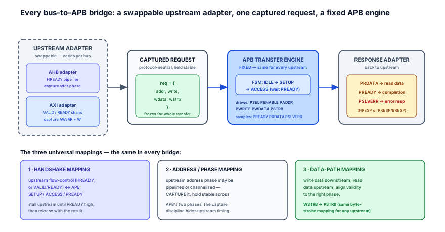
The three universal mappings every bus-to-APB bridge performs — handshake mapping, address/phase capture, and data-path (byte-strobe) routing — around a common APB transfer engine. Learn the pattern once and any specific bridge (AHB or AXI) is an instantiation with a swappable upstream adapter.
You have now seen two concrete bridges in detail: the AHB-to-APB bridge and the AXI-to-APB bridge. They look different — one collapses a two-phase pipeline, the other demultiplexes five channels — but if you squint they are doing the same three things. This chapter extracts that pattern. The single idea to carry: every bus-to-APB bridge is the same three mappings — handshake, address/phase, and data-path — wrapped around one fixed APB transfer engine, with only the upstream adapter changing. Learn the three mappings and the capture discipline once, and any specific bridge becomes an instantiation you can read, design, debug, and defend on sight.
1. Problem statement
The problem is finding the protocol-conversion pattern that is common to every bus-to-APB bridge, so that you reason about one set of mechanics instead of memorising each bridge as a special case.
A bridge takes a transaction expressed in one bus's grammar and re-expresses it in APB's grammar. Strip away the specifics of the upstream bus and exactly three translation problems remain — and they are always the same three:
- Handshake mapping. The upstream bus flow-controls in its own dialect — AHB with
HREADY, AXI with per-channelVALID/READY. APB flow-controls with theSETUP → ACCESS → PREADYsequence. The bridge must convert the upstream "go" into an APB transfer launch, hold the upstream stalled untilPREADYcompletes, and convert the APB completion back into the upstream's "done." - Address/phase mapping. The upstream address arrives in a phase the bridge does not control — pipelined ahead (AHB) or on a separate channel that handshakes independently of the data (AXI). APB needs that address held stable across its whole two-phase transfer. The bridge must capture the upstream address (and write attributes) the instant it accepts the request, then drive APB from the capture.
- Data-path mapping. Write data must be routed downstream with its byte strobes (
WSTRB → PSTRB), and read data routed upstream — each aligned to the correct phase so the slave samples valid data and the master receives valid data. Validity does not align by accident; the bridge must place each beat in the right phase.
The job, abstractly, is therefore: an upstream adapter turns the bus's transaction into a captured, protocol-neutral request, a fixed APB transfer engine drives that request as one APB transfer, and a response adapter returns the result. The APB side is a fixed target; only the upstream adapter varies.
2. Why previous knowledge is insufficient
You have two fully worked bridges, but each was taught as a specific block, and that is exactly what this chapter must transcend.
- The AHB-to-APB chapter taught one upstream dialect. 13.1 framed the bridge as an AHB slave that captures the pipelined address phase and stalls
HREADY. That is the handshake and address mappings — but specialised to AHB's pipeline (AHB's two-phase pipeline, what HREADY means). You have not yet abstracted "capture the pipelined address" into the general rule "capture whatever phase the upstream uses." - The AXI-to-APB chapter taught a different upstream dialect. 13.2 framed the same job around AXI's five independent channels and VALID/READY handshake — capturing AW/AR + W into a request and serialising onto APB. Seen alone it looks like a new problem; seen beside 13.1 it is the same three mappings with a different adapter. Without putting them side by side you cannot see that the APB transfer engine in both is byte-for-byte the same.
- You have not yet named the invariant. Neither prior chapter said out loud: the APB side never changes; only the upstream adapter does. That invariant is the whole point of an abstraction chapter — it is what lets you build a reusable APB engine, write one bridge checker, and treat a new upstream bus as "write a new adapter," not "design a new bridge."
- The two hard mappings are deferred to dedicated chapters. The depth of the handshake mapping — how an APB wait actually propagates upstream beat by beat — lives in wait-state propagation (13.4). The depth of the error mapping — how
PSLVERRbecomes the upstream error response — lives in error propagation (13.5). This chapter establishes the structure; those two drill the mechanics.
So the model to add is the abstraction itself: the three mappings, the captured generic request, and the fixed-engine / swappable-adapter split that makes any specific bridge an instantiation.
3. Mental model
The model: a bridge is a translation pipeline with a universal core and a swappable front-end — like a power adapter whose internal regulator is always the same and only the wall plug changes per country. The wall plug (the upstream adapter) speaks AHB or AXI; the regulator (the APB transfer engine) is identical everywhere; in between sits a normalised "DC bus" — the captured generic request — that hides which plug was used.
Three refinements make it precise:
- Normalise to a captured generic request. Whatever the upstream bus, the adapter reduces an accepted transaction to one protocol-neutral record —
{addr, write, wdata, wstrb}— and freezes it. This capture is the linchpin: it is where the address/phase mapping happens, and it decouples the upstream's pipelining or channelisation from APB's serial cadence. After capture, the downstream engine never sees AHB or AXI — only a stable request. - The APB transfer engine is fixed and reusable. It runs the unchanging
IDLE → SETUP → ACCESSFSM, drivesPSEL/PENABLE/PADDR/PWRITE/PWDATA/PSTRBfrom the captured request, and samplesPREADY/PRDATA/PSLVERR. It does not know or care what produced the request. Because APB is the fixed two-phase target, this engine is byte-for-byte identical across the AHB and AXI bridges — that is why it can be reused. - The three mappings are the only moving parts. Handshake: upstream "go" → APB launch, and
PREADY→ upstream "done," with the upstream stalled in between. Address/phase: capture the upstream address into the request, immune to whatever the upstream phase does next. Data-path:wdata/wstrb→PWDATA/PSTRBdownstream,PRDATA→ read data upstream, each in the right phase. Every bridge is exactly these three mappings around the fixed engine.
4. Real SoC implementation
In RTL the abstraction is literal: an upstream adapter produces a captured generic request struct, a fixed APB transfer engine consumes it, and a response adapter maps the result back. Swapping AHB for AXI swaps only the adapter — the engine below is untouched.
// ============================================================================
// Generic bus-to-APB bridge: swappable upstream adapter -> FIXED APB engine.
// The engine never knows which upstream produced the request.
// ============================================================================

// --- Protocol-neutral captured request: the normalised "DC bus" ---------------
typedef struct packed {
  logic [31:0] addr;     // captured upstream address  (address/phase mapping)
  logic        write;    // 1 = write, 0 = read
  logic [31:0] wdata;    // captured write data        (data-path mapping)
  logic [3:0]  wstrb;    // captured byte strobes -> PSTRB (data-path mapping)
} apb_req_t;

// --- Upstream adapter (THIS is the only part that varies per bus) -------------
// Its whole job: do the HANDSHAKE mapping (accept the upstream "go"),
// the ADDRESS/PHASE mapping (CAPTURE addr/write before the phase moves on),
// and present a stable apb_req_t + a one-cycle 'req_valid' pulse to the engine.
// For AHB: req_valid = hsel & hready_in & htrans[1]; capture haddr/hwrite/hwdata.
// For AXI: req_valid = (awvalid & wvalid) | arvalid; capture ax_addr/wdata/wstrb.
apb_req_t req;          // <-- driven by the adapter, held stable until 'done'
logic     req_valid;    // <-- one transfer offered
logic     done;         // <-- engine pulses this when PREADY completes
// (the adapter de-asserts upstream ready / advances its channel on 'done')

// --- FIXED APB transfer engine: identical for AHB, AXI, or any future bus ------
typedef enum logic [1:0] {IDLE, SETUP, ACCESS} apb_state_t;
apb_state_t state, nstate;

always_comb begin
  nstate = state;
  unique case (state)
    IDLE:   if (req_valid) nstate = SETUP;     // HANDSHAKE: upstream "go" -> launch
    SETUP:                 nstate = ACCESS;     // SETUP is always exactly one cycle
    ACCESS: if (pready)    nstate = IDLE;       // hold here until APB completes
  endcase
end
always_ff @(posedge pclk or negedge presetn)
  if (!presetn) state <= IDLE; else state <= nstate;

// APB outputs driven straight from the CAPTURED request (never live upstream sigs)
assign psel    = (state == SETUP) || (state == ACCESS);
assign penable = (state == ACCESS);
assign paddr   = req.addr;                       // address/phase mapping result
assign pwrite  = req.write;
assign pwdata  = req.wdata;                       // data-path: write data downstream
assign pstrb   = req.wstrb;                       // data-path: WSTRB -> PSTRB, 1:1

// Completion pulse the adapter waits on (HANDSHAKE mapping, return direction)
assign done    = (state == ACCESS) && pready;

// --- Response adapter: map the APB result back into the upstream's grammar -----
// Read data goes up; PSLVERR becomes the upstream error response.
// (The engine just exposes the raw APB result; the adapter re-dresses it.)
assign rdata_up = prdata;                         // data-path: read data upstream
assign err_up   = done && pslverr;                // -> HRESP=ERROR / RRESP/BRESP=SLVERR
Two facts make this the canonical pattern. First, the captured request is the abstraction boundary: above it the adapter speaks AHB or AXI; below it the engine speaks only APB. Because the engine reads exclusively from req (never from live upstream signals), it is literally the same module in both bridges — which is the whole claim of this chapter made concrete. Second, the three mappings are localised to three places: the handshake mapping is the req_valid/done contract between adapter and engine (its depth is wait-state propagation); the address/phase mapping is the capture inside the adapter; the data-path mapping is wstrb → pstrb plus prdata routing. Change the upstream and you rewrite only the adapter — the engine and the data-path 1:1 strobe map are invariant.
5. Engineering tradeoffs
Each mapping is realised differently depending on the upstream bus, but the structure of the choice is identical. This table is the heart of the abstraction: the three mappings across an AHB upstream, an AXI upstream, and the fixed APB downstream.
| Mapping | AHB upstream | AXI upstream | APB downstream (fixed) |
|---|---|---|---|
| Handshake | Stall by holding HREADY=0 from launch until PREADY; accept on HSEL & HREADY & HTRANS[1] | Hold AWREADY/ARREADY/WREADY low until the engine can take the beat; signal completion on BVALID/RVALID; accept when AW+W (or AR) handshake | SETUP → ACCESS, wait for PREADY; one transfer at a time, no pipeline — the engine's req_valid/done contract |
| Address/phase | Capture the pipelined address phase (HADDR/HWRITE/HSIZE) on accept — it advances to the next transfer otherwise | Capture the channel address (AWADDR/ARADDR) when its channel handshakes, independently of the data beat | PADDR/PWRITE held stable across both phases — driven from the captured req, never live upstream |
| Data-path | Capture HWDATA in the AHB data phase; route HRDATA up; map AHB byte lanes / HSIZE to PSTRB | Capture WDATA/WSTRB from the W channel; route RDATA up; WSTRB → PSTRB directly (both are byte strobes) | PWDATA/PSTRB driven in SETUP/ACCESS from req; PRDATA sampled at PREADY; PSTRB is the same byte-strobe idea on both sides |
The throughline: read the table by column and you see two different upstream adapters; read it by row and you see three problems that are conceptually identical regardless of upstream. The APB column never changes — that is the fixed engine. Designing a bridge for a new upstream bus is filling in a fourth column for that bus, against the same three rows; you never touch the APB column or the row definitions.
6. Common RTL mistakes
7. Debugging scenario
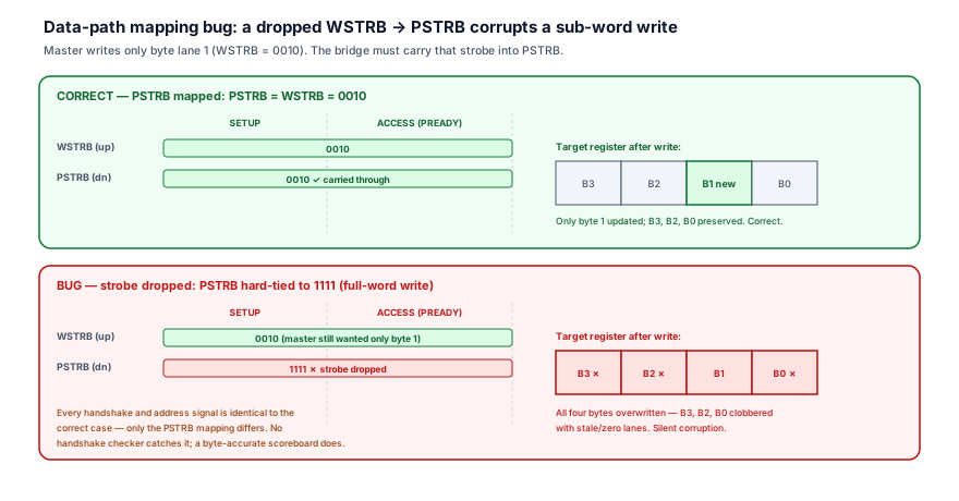
The signature generic-mapping failure is a broken data-path mapping that drops the byte strobe — the bridge launches a clean APB transfer with the right address and handshake, but PSTRB does not carry WSTRB, so a sub-word write corrupts the bytes the master never meant to touch.
- Observed symptom: a driver does a byte write to a packed peripheral register — say it updates only the control byte of a 32-bit register — and the other three bytes of the same register come back changed on the next read. Full-word writes work perfectly; only sub-word (byte/half-word) writes corrupt neighbouring fields. It reproduces on both the AHB and AXI bridges, which points at the shared engine, not an upstream adapter.
- Waveform clue: on the upstream side
WSTRB(or the AHB lane/HSIZEencoding) shows0010— one byte enabled. On the APB side, in the same ACCESS phase,PSTRBreads1111. Every other signal is correct:PADDRis the right register,PSEL/PENABLE/PREADYsequence cleanly,PWDATAcarries the byte in the right lane. OnlyPSTRBdisagrees withWSTRB. - Root cause: the data-path mapping dropped the strobe. The engine drove
pstrb = '1(a hard-tied full-word strobe) instead ofpstrb = req.wstrb, so the slave treated every transfer as a full 32-bit write and clobbered the three lanes the master left disabled with whatever the unusedPWDATAlanes held. The handshake and address mappings were flawless, which is exactly why no protocol checker fired. - Correct RTL: carry the captured strobe through the engine unchanged —
assign pstrb = req.wstrb;— and ensure the adapter populatesreq.wstrbfrom the real upstream strobe (WSTRBon AXI; the byte-lane/HSIZE-derived strobe on AHB). The byte-strobe map is part of the fixed engine's contract, not an upstream afterthought. - Verification assertion: assert the strobe is mapped 1:1 on every write, and that a sub-word write never asserts lanes the master did not —
assert property (@(posedge pclk) disable iff(!presetn) (psel && pwrite && penable) |-> (pstrb == req.wstrb));paired with a byte-accurate scoreboard check that disabled lanes of the target register are$stableacross the write. - Debug habit: when a write succeeds (right address, clean handshake, no error) but neighbouring bytes corrupt, suspect the data-path mapping, specifically the byte strobe — not the handshake or address. Diff
WSTRBagainstPSTRBin the same phase: if a sub-word strobe became all-ones, the mapping dropped it. A clean handshake with corrupted data is the fingerprint of a data-path bug, which per-protocol handshake monitors will pass right over.
8. Verification perspective
A bridge is verified as two compliant interfaces plus the three mappings between them — and the abstraction pays off here: because the mappings are universal, you write one reusable checker and re-target it at any upstream.
- Verify each mapping independently, not just "the transfer worked." A transfer can pass end-to-end while a mapping is subtly broken. (1) Handshake mapping: assert the upstream is stalled for the full APB transfer and released only at
PREADY, and that the engine never launches a second APB transfer before the first completes. (2) Address/phase mapping: assertPADDR/PWRITEare$stableacross the whole APB transfer and equal the captured request. (3) Data-path mapping: assertPSTRB == req.wstrbandPWDATA == req.wdataon writes, and thatPRDATAis sampled and forwarded atPREADYon reads. Splitting the checks isolates which mapping failed when a directed test corrupts data. - Assert captured-request stability — the capture discipline is testable. The address/phase mapping's correctness reduces to one property: once the engine accepts a request, the request it drives onto APB does not change until
done.assert property (@(posedge pclk) disable iff(!presetn) (state != IDLE) |-> $stable(req));This single property catches the entire class of "wired live upstream signal through instead of capturing" bugs, regardless of upstream — it is the abstraction's payoff in one line. - Build a reusable, upstream-agnostic bridge checker. Because the engine consumes only the generic request and produces only APB outputs, a checker bound to the
req → APBboundary works unchanged for the AHB bridge, the AXI bridge, and any future upstream. It needs an abstract transaction model ({addr, write, wdata, wstrb}) and the APB monitor; the upstream-specific VIP sits above it. One scoreboard, re-targeted by swapping the upstream driver, verifies every bridge's core — exactly mirroring the RTL's swappable-adapter / fixed-engine split.
The point: verify the three mappings separately, assert the captured request is stable, and write the boundary checker against the generic request so it is reusable — the universality of the mappings is what makes one verification environment cover every bus-to-APB bridge.
9. Interview discussion
"What's common to an AHB-to-APB and an AXI-to-APB bridge?" — or "design a generic bridge to APB" — separates candidates who memorised two bridges from those who understand the pattern.
Lead with the structure: every bus-to-APB bridge is an upstream adapter producing a captured generic request, a fixed APB transfer engine, and a response adapter — and the APB side is a fixed target while only the adapter varies. Then name the three mappings crisply: handshake (upstream flow-control ↔ APB SETUP/ACCESS/PREADY, with the upstream stalled until completion), address/phase (capture the upstream address — pipelined for AHB, channelised for AXI — and hold it stable across APB's two phases), and data-path (write data + WSTRB → PSTRB downstream, read data upstream, each aligned to the right phase). The depth that marks a senior answer: explain why capture is mandatory (the upstream phase moves before APB completes), point out that WSTRB → PSTRB is one byte-strobe mapping not two problems, and state that the APB engine must read only the captured request so it is reusable. Close with the payoff — "because the engine and the mappings are invariant, you write the APB core and the bridge checker once; a new upstream is a new adapter, not a new bridge" — and note that the hard parts, wait-state and error propagation, are where the handshake and error mappings get their full depth. That framing shows you can abstract, which is exactly what the question tests.
10. Practice
- Name the four stages. For a generic bus-to-APB bridge, list the four pipeline stages in order and state which one is fixed across all upstreams and which one varies.
- List the three mappings. Write the three universal mappings and, for each, give the upstream side (pick AHB or AXI) and the APB side.
- Justify the capture. Explain, in terms of the upstream phase, why the address/phase mapping must capture rather than wire through — and give one concrete way it breaks if you don't.
- Map the strobe. State what
WSTRBbecomes on the APB side, why it is one mapping rather than two, and what corrupts if the bridge ties the downstream strobe to all-ones. - Reuse the checker. Explain why a checker bound to the captured-request → APB boundary works unchanged for both the AHB and AXI bridges, and what part of the environment you do have to swap per upstream.
11. Q&A
12. Key takeaways
- Every bus-to-APB bridge is one pattern: an upstream adapter → a captured generic request
{addr, write, wdata, wstrb}→ a fixed APB transfer engine → a response adapter. The APB side is a fixed target; only the upstream adapter varies. - There are exactly three universal mappings: handshake (upstream flow-control ↔ APB
SETUP/ACCESS/PREADY), address/phase (capture the upstream address and hold it stable across APB's two phases), and data-path (WSTRB → PSTRBand write data down, read data up, each aligned to the right phase). - Capture is the linchpin. The upstream address lives in a phase you don't control — pipelined (AHB) or channelised (AXI) — so it must be registered into the generic request; the engine drives APB only from the capture, never from live upstream signals. This both prevents corruption and enables reuse.
WSTRB → PSTRBis one byte-strobe mapping, not two problems. Carry it 1:1; dropping it (tyingPSTRBhigh) silently turns sub-word writes into byte corruption that no handshake checker catches.- The engine is reusable because it reads only the generic request. Any upstream-awareness in the engine is a leak; the abstraction is what lets you write the APB core, the stability/strobe assertions, and the bridge checker once and re-target them per upstream.
- The specific bridges are instantiations. AHB-to-APB and AXI-to-APB differ only in the adapter; the hard mappings get their full depth in wait-state propagation and error propagation.