AMBA AHB · Module 9
Lane Selection
The general AHB lane-selection rule — for a bus W bytes wide, an access of S bytes at address A uses S consecutive byte lanes starting at the byte offset (A mod W) — generalizing the byte/halfword/word lane usage to any bus width.
Chapter 9.2 showed how byte, halfword, and word transfers use the lanes on a 32-bit bus. This chapter gives the general rule for any bus width: for a data bus W bytes wide, an access of S bytes at address A uses S consecutive byte lanes starting at the byte offset (A mod W). So the size (S = 2^HSIZE) gives how many lanes, and the low log2(W) address bits (the byte offset, A mod W) give where they start. Because the access is naturally aligned (chapter 9.3), those S lanes form a contiguous, aligned group within the bus word. This single rule subsumes the byte/halfword/word cases of chapter 9.2 and extends to any bus width (32-, 64-, 128-bit, …) and any size — the complete derivation of the active byte lanes from HSIZE and the address.
1. What Is It?
The lane-selection rule: for a data bus W bytes wide, an access of S bytes (S = 2^HSIZE) at address A uses the S consecutive byte lanes starting at byte offset (A mod W).
- How many lanes comes from the size: S =
2^HSIZEconsecutive lanes (word = 4, halfword = 2, byte = 1). - Where they start comes from the low
log2(W)address bits: the byte offset within the bus word,A mod W(on a 32-bit bus, the low 2 bits; on a 64-bit bus, the low 3 bits).
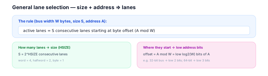
So the rule is size + address → lanes, made precise: the count is S (from HSIZE), the starting lane is the byte offset A mod W (from the low address bits), and the active lanes are the S consecutive lanes from there. Natural alignment guarantees these S lanes stay within one bus word and form a contiguous, aligned group (a word fills an aligned W-byte group, a halfword an aligned pair, a byte one lane) — never straddling the bus-word boundary or forming a non-aligned group (which would require an unaligned access, chapter 9.4). This rule generalizes chapter 9.2 (which was the 32-bit, byte/halfword/word special case) to any W and any S.
2. Why Does It Exist?
The lane-selection rule exists because the data bus is byte-lane-organized — each byte of the bus word is a lane — and a transfer must place its bytes on the correct lanes so the data lands at the right byte positions in memory (and the right lanes are read).
The data bus of width W bytes is divided into W byte lanes, each carrying one byte of the bus word at a fixed byte position. A transfer's data must go on the lanes corresponding to its byte addresses: a byte at address A goes on the lane for byte position A mod W; a multi-byte access goes on the consecutive lanes for its bytes. So the lane selection exists to route each byte to its correct lane — the lane is determined by the byte's position within the bus word, which is its address mod W. This is fundamental: the bus is byte-organized, so each byte must travel on its byte's lane. The rule formalizes this — the access's bytes go on the S consecutive lanes starting at its byte offset.
The reason the size gives the count is that the access moves S bytes, so it occupies S consecutive lanes — one per byte. A word (4 bytes) needs 4 lanes, a halfword 2, a byte 1. So the size directly determines how many lanes the access uses. And the reason the low address bits give the start is that the byte offset A mod W is the position of the access's first byte within the bus word — which is the starting lane. So size (count) and address (start) together pinpoint the exact lanes: S lanes from the offset. This decomposition — count from size, start from address — is the natural way to specify a contiguous range of lanes.
The reason the rule produces a contiguous, aligned group (not arbitrary lanes) is natural alignment (chapter 9.3): because the access is aligned to its size, its byte offset A mod W is a multiple of S, so the S consecutive lanes from there form an aligned group within the bus word (and don't cross the bus-word boundary). For example, an aligned word starts at offset 0 (or W/2 on a wider bus) and fills an aligned W-byte... — the point is the alignment makes the lane group clean. So the rule, combined with natural alignment, always gives a contiguous aligned lane group — which is what keeps the lane logic simple (chapter 9.4). The rule exists in this clean form because accesses are aligned; without alignment, the "S lanes from offset" could be a non-aligned group, which AHB doesn't support.
3. Mental Model
Model lane selection as placing a row of dominoes of a given length at a marked starting position on a numbered track — the length (size) says how many tiles, the start mark (address offset) says where, and the tiles occupy a contiguous run from there.
A numbered track (the byte lanes, 0 to W−1) holds tiles. You place a run of tiles representing your data: the length of the run (the access size S) says how many tiles, and the starting mark (the byte offset A mod W) says where the run begins. So you lay S contiguous tiles starting at position (A mod W): a 1-tile run (byte) at the marked position, a 2-tile run (halfword) from there, a 4-tile run (word) from there. The tiles occupy a contiguous run — and because the marks are placed at aligned positions (natural alignment), the run is aligned and stays within the track's word. The empty positions (other lanes) aren't used. So the run's length and start fully determine which positions it occupies — exactly size and address determining the lanes.
This captures lane selection: the numbered track = the W byte lanes; the run's length = the access size (how many lanes); the starting mark = the byte offset A mod W (where they start); the contiguous run = the S consecutive active lanes; aligned marks = natural alignment giving a contiguous aligned group. Length and start ⇒ the occupied positions.
Watch lane selection for various accesses:
Lane selection from size and address (64-bit bus)
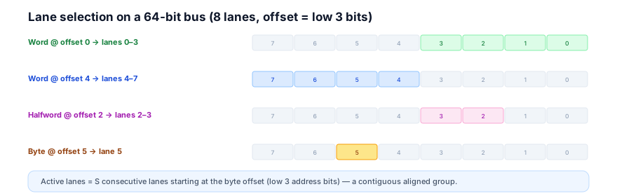
4 cyclesThe model's lesson: lay S contiguous lanes starting at the byte offset (A mod W). In the waveform, each access's active lanes are the S consecutive lanes from its offset — word@0 → 0–3, word@4 → 4–7, halfword@2 → 2–3, byte@5 → 5. Size gives the run length, the offset gives the start; alignment keeps the run aligned within the bus word.
4. Real Hardware Perspective
In hardware, lane selection is a small combinational decoder that takes HSIZE and the low address bits and produces a lane-active mask (one bit per byte lane) — used as byte-write-enables for writes and valid-lane indicators for reads.
The lane decoder computes, for each byte lane, whether it's active for the current transfer. Active lane i is one whose byte position falls in [offset, offset + S − 1], where offset = A mod W and S = 2^HSIZE. So the decoder is a function of HSIZE (giving S) and the low log2(W) address bits (giving the offset), producing a W-bit lane-active mask. This is a small, fast combinational block — a decode of size and offset into a contiguous run of active bits. Because of natural alignment, the run is always aligned, so the decoder only produces aligned masks (a word mask covers an aligned W... group, a halfword an aligned pair, a byte one bit) — simpler than handling arbitrary masks.
The lane-active mask's uses mirror chapter 9.2, now generalized:
For a write, the lane-active mask is the byte-write-enable — the slave captures only the active HWDATA lanes (so a sub-word write modifies only its bytes). For a read, it's the valid-lane indicator — the slave drives the active HRDATA lanes with valid data. So the same mask serves both, generalizing the 32-bit byte/halfword/word behavior to any bus width and size. The mask is the central output of lane selection — it governs the byte-lane data handling for the transfer.
A hardware note on alignment of the data to the lane: a byte at offset k goes on lane k (its byte position). For a multi-byte access, byte j of the access goes on lane offset + j. So the data's byte positions map directly to lanes by their addresses. This means the placement of each byte on its lane is determined by its address — which is why the lane decoder uses the low address bits. (The endianness, chapter 9.6, affects how a multi-byte value's bytes map to addresses, hence to lanes — but the lane-from-address rule is the same.) So in hardware, each byte travels on the lane for its byte address, and the lane decoder computes the active set from HSIZE + the offset.
The generalization to any W is clean: the rule (S lanes from offset A mod W) works for W = 4 (32-bit, low 2 address bits), W = 8 (64-bit, low 3 bits), W = 16 (128-bit, low 4 bits), etc. — only the number of low address bits (log2 W) and the number of lanes (W) change. So the lane decoder scales to any bus width by parameterizing on W. This is why the general rule is valuable: it's one rule for all bus widths, and the byte/halfword/word-on-32-bit case (chapter 9.2) is just W = 4. So the hardware lane decoder is a parameterized version of the same logic across bus widths.
5. System Architecture Perspective
At the system level, lane selection is the mechanism that lets any access size work on any bus width — placing each access's data on the correct lanes — and it is central to bridges and width converters that connect buses of different widths.
The any-size-on-any-width capability is the system benefit: the general lane rule means a system can use any bus width (32, 64, 128 bits) and any access size (up to the width), with the lane decoder routing each access correctly. So the lane selection is what makes the bus flexible across sizes and widths — a byte, halfword, word, or wider access, on a bus of any width, all handled by the same rule. This flexibility is essential: systems have diverse access sizes and choose bus widths for bandwidth, and lane selection ties them together. So lane selection is the glue that makes mixed-size access on any-width buses work.
The bridges and width converters are where lane selection is most architecturally significant (foreshadowing chapter 9.7). When connecting buses of different widths (e.g., a 64-bit bus to a 32-bit peripheral bus, or AHB to APB), a bridge must translate the lane usage: an access on the wide bus maps to the right lanes/bytes on the narrow bus, possibly splitting a wide access into multiple narrow ones. So the bridge uses the lane-selection rule on both sides to route the bytes correctly. This is a key system function: width conversion relies on understanding which lanes each access uses, on each bus. The lane-active mask (and the byte addresses) tell the bridge how to map the data. So lane selection underpins width conversion — a common system need when connecting buses of different widths.
The endianness interaction (chapter 9.6) is a system-wide convention layered on lane selection: the lane-from-address rule is fixed (a byte goes on the lane for its byte address), but which byte of a multi-byte value sits at which address — and hence which lane — depends on the system's endianness. So lane selection and endianness together define the complete data placement. A system must have a consistent endianness so that all components agree on how multi-byte values map to lanes. So at the system level, lane selection (the size+address→lanes rule) plus endianness (the value→bytes→addresses mapping) form the full data-placement convention — which all components must share for correct data interchange. Lane selection is the size/address part; endianness is the value-byte-ordering part; together they place every byte on its lane. So lane selection is foundational to the system's data-placement convention, working with endianness to ensure bytes land correctly across all components and bus widths.
6. Engineering Tradeoffs
Lane selection embodies the size-plus-address-to-contiguous-lanes design.
- General rule vs per-size cases. One general rule (S lanes from offset A mod W) covers all sizes and bus widths, at the cost of a parameterized decoder. Per-size, per-width special cases would be more code/logic and less uniform. The general rule is cleaner and scales.
- Contiguous aligned lanes (alignment) vs arbitrary. Relying on natural alignment to keep the lane group contiguous and aligned makes the decoder simple (only aligned masks), at the cost of not supporting unaligned (non-aligned-group) accesses. AHB's alignment requirement (chapter 9.3) enables this simplicity.
- Mask serves both reads and writes. Using the same lane-active mask for byte-write-enables (writes) and valid-lane indicators (reads) is uniform and economical, at the minor cost of interpreting it per direction. One mask, two uses — efficient.
- Parameterize on W vs fixed width. Making the lane rule/decoder parameterized on bus width W lets the same logic serve 32/64/128-bit buses, at the cost of the parameterization. A fixed-width decoder would be simpler but not reusable. The parameterized rule is general.
The throughline: lane selection derives the active byte lanes as the S consecutive lanes starting at byte offset (A mod W) — size (S = 2^HSIZE) gives the count, the low address bits give the start, and natural alignment makes the group contiguous and aligned. A small combinational decoder produces the lane-active mask (byte-write-enables for writes, valid lanes for reads), parameterized on any bus width W. The rule generalizes the byte/halfword/word cases to any size and width, and underpins width conversion in bridges. It's the complete, uniform derivation of lanes from HSIZE and the address.
7. Industry Example
Trace lane selection across accesses on a 64-bit bus, and in a width-converting bridge.
A system has a 64-bit AHB (8 byte lanes) with memory and peripherals, plus a bridge to a 32-bit peripheral bus.
- A word on the 64-bit bus. The processor reads a 32-bit word at an address with offset 0 (within the 64-bit word). The lane decoder (HSIZE=word → S=4, offset=0) activates lanes 0–3. The word's data is on lanes 0–3. A word at offset 4 would activate lanes 4–7. So the same word size maps to different lanes depending on the offset (the low 3 address bits).
- A halfword on the 64-bit bus. A halfword at offset 2 (HSIZE=halfword → S=2, offset=2) activates lanes 2–3. At offset 6, lanes 6–7. The 2-lane group is placed by the offset.
- A byte on the 64-bit bus. A byte at offset 5 (S=1, offset=5) activates lane 5 alone. Any of the 8 lanes can be the single active lane, selected by the low 3 address bits.
- A sub-word write — byte-write-enables. A byte write at offset 5 enables only lane 5's byte-write-enable, so the memory modifies one byte and preserves the other seven. The lane-active mask is the byte-write-enable. This generalizes the 32-bit byte-write-enable behavior to the 64-bit bus.
- The width-converting bridge. The 64-bit-to-32-bit bridge translates accesses. A 64-bit (8-byte) access on the wide bus maps to two 32-bit accesses on the narrow bus (the high and low halves), with the bridge using lane selection to route the bytes. A 32-bit word access on the wide bus (offset 0 or 4) maps to a single 32-bit access on the narrow bus, with the lanes mapped correctly. So the bridge relies on lane selection (on both buses) to convert the width — placing each byte on the right lane on each side. This is where the general lane rule is essential: the bridge must compute lanes on both the 64-bit and 32-bit sides.
- Endianness consistency. Throughout, the system's endianness (chapter 9.6) determines how multi-byte values' bytes map to addresses (hence lanes), and the bridge preserves this. So lane selection (size+address→lanes) and endianness (value→bytes→addresses) together place each byte correctly across the width conversion.
The example shows lane selection on a 64-bit bus (S lanes from the offset, for word/halfword/byte), the byte-write-enable use for sub-word writes, and — crucially — its role in a width-converting bridge, which uses the lane rule on both bus widths to route bytes correctly. The general rule (S lanes from offset A mod W) handles all sizes and both bus widths, which is what makes the bridge's width conversion work.
8. Common Mistakes
9. Interview Insight
Lane selection is a precise interview check — the general "S lanes from offset (A mod W)" rule, with size and address roles, is the signal.
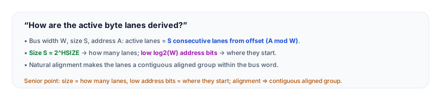
The answer that lands states the general rule and the two roles: "The active byte lanes are derived from the size and the low address bits. For a data bus W bytes wide, an access of S bytes at address A uses S consecutive byte lanes starting at the byte offset, which is A mod W. So the size — S equals 2 to the HSIZE — gives how many lanes (word = 4, halfword = 2, byte = 1), and the low log2(W) address bits give the byte offset, which is where the lanes start. For example, on a 64-bit bus, a word at offset 0 uses lanes 0–3, a word at offset 4 uses lanes 4–7, a halfword at offset 2 uses lanes 2–3, a byte at offset 5 uses lane 5. Because accesses are naturally aligned, those S lanes always form a contiguous, aligned group within one bus word. In hardware it's a small decoder from HSIZE and the low address bits to a lane-active mask, which serves as byte-write-enables for writes and valid-lane indicators for reads. The rule is general — it works for any bus width; the 32-bit byte/halfword/word case is just W equals 4." The general rule, the size/address roles, and the contiguous-aligned-group property are the senior signals.
10. Practice Challenge
Apply the lane rule.
- State the rule. Give the general lane-selection rule and what the size and address each contribute.
- 64-bit examples. Give the active lanes for a word at offset 0, a halfword at offset 6, and a byte at offset 3 on a 64-bit bus.
- Both inputs. Explain why a halfword at offset 0 and at offset 2 use different lanes.
- The mask's uses. Explain how the lane-active mask is used for writes versus reads.
- Bridges. Explain how a width-converting bridge uses lane selection.
11. Key Takeaways
- The general lane rule: for a bus W bytes wide, an access of S bytes at address A uses S consecutive byte lanes starting at byte offset (A mod W).
- Size gives the count, address gives the start — S =
2^HSIZEis how many lanes; the lowlog2(W)address bits are the byte offset (where they start). Both are needed. - Natural alignment makes the lanes a contiguous, aligned group within one bus word (never straddling the boundary or forming a non-aligned group).
- A small combinational decoder produces the lane-active mask — byte-write-enables for writes, valid-lane indicators for reads — from HSIZE and the low address bits.
- The rule generalizes to any bus width — the 32-bit byte/halfword/word case (chapter 9.2) is just W = 4; it scales to 64-, 128-bit, etc.
- Lane selection underpins width-converting bridges — they apply the rule on both bus widths to route bytes correctly (and works with endianness to place each byte).
12. What Comes Next
You now have the general lane-selection rule. The next chapters cover endianness and the downstream use of size/lane info:
- 9.6 — Endianness Considerations (coming next) — big- vs little-endian byte placement on the data bus.
- 9.7 — Write Strobes in Bridges (coming soon) — how size/lane info becomes write strobes downstream.
To revisit the 32-bit lane cases, see Byte, Halfword & Word Transfers; for the alignment that keeps the lanes contiguous, Aligned Access and Unaligned Access Rules. For the HSIZE encoding, HSIZE Encoding. For the broader protocol map, see the AMBA family overview.