Introduction to VHDL
The design of any digital system starts with writing its specifications. These originate from customer requirements and are communicated to ASIC companies through the marketing team.
Once specifications are ready, the system is designed at the block level, and later implemented at the RTL (Register Transfer Level) using coding. RTL coding can be done in VHDL, Verilog, or SystemVerilog.
Earlier, when synthesis and simulation tools were not available, designers had to verify everything manually on paper. But today, EDA (Electronic Design Automation) tools make this process much faster and more accurate.
-
Synthesis tools: Quartus (Intel), Vivado (Xilinx)
-
Simulation tools: Questa (Siemens), Xcelium (Cadence)
These tools have significantly reduced the time needed for synthesis and simulation.
VHDL is a disciplined and strongly typed language, originally developed for the U.S. Department of Defense, and inspired by the syntax of the ADA programming language.
Verilog, on the other hand, is designed with C-like syntax, making it simpler and faster to learn for engineers.
Even today, preferences vary:
-
Europe → VHDL is highly preferred
-
Defense and Aerospace → Rely on VHDL because of its strict and structured nature
VHDL enforces a strict coding style with its own structure (e.g., Entity, Architecture, Records, Libraries). Unless all the required libraries are included, synthesis cannot proceed. This ensures discipline, clarity, and reliability in the design process.
Why VHDL when Verilog already exists?
Think about our daily life — we often see systems around us that take some input and produce the desired output.
For example, consider a TV: when we press the volume up/down button on the remote, the output we get is the increase or decrease in the sound level of the TV.
Here:
-
Input = the command sent via IR signal from the remote
-
Output = change in the speaker volume (measured in dB)
-
System Design = the logic inside the TV that processes the input and controls the power of the speaker to increase or decrease the sound.
So, from this simple daily-life example, you can understand the core concept:
Every digital system takes an input and produces an output that matches the required specification.
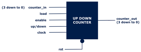
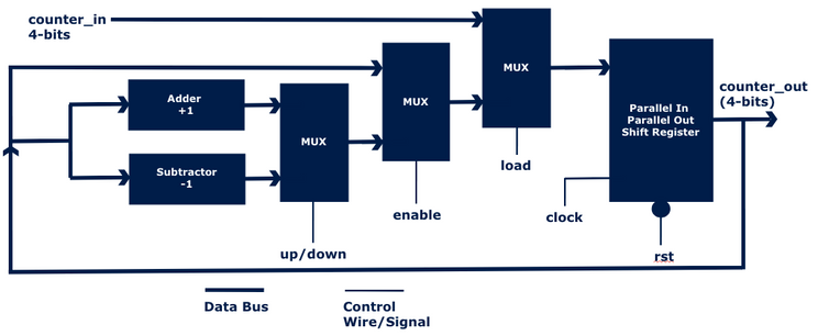
Now, let’s take a classic digital design example: the Asynchronous Up/Down Counter.
Instead of memorizing the counter design from textbooks, let us understand it logically.
A Counter typically has the following signals:
-
clk (clock)
-
rst (reset)
-
counter_in (input data to load)
-
load (control signal to load counter_in)
-
enable (to allow counting)
-
counter_out (the output value of the counter)
Core Concepts
RTL Code
VHDL
LIBRARY IEEE;
USE IEEE.std_logic_1164.all;
USE IEEE.numeric_std.all;
ENTITY counter IS
PORT (
clock : IN std_logic;
rst : IN std_logic;
ENABLE : IN std_logic;
LOAD : IN std_logic;
UP_DOWN : IN std_logic;
counter_in : IN std_logic_vector(3 DOWNTO 0);
counter_out : OUT std_logic_vector(3 DOWNTO 0)
);
END counter;
ARCHITECTURE behavioral OF counter IS
SIGNAL counter_out_tmp : unsigned(3 DOWNTO 0); -- unsigned type for arithmetic
BEGIN
counter_proc : PROCESS (rst, clock)
BEGIN
IF (rst = '0') THEN
counter_out_tmp <= (OTHERS => '0');
ELSIF rising_edge(clock) THEN
IF (LOAD = '1') THEN
counter_out_tmp <= unsigned(counter_in);
ELSIF (ENABLE = '1') THEN
IF (UP_DOWN = '1') THEN
counter_out_tmp <= counter_out_tmp + 1;
ELSE
counter_out_tmp <= counter_out_tmp - 1;
END IF;
END IF;
END IF;
END PROCESS;
counter_out <= std_logic_vector(counter_out_tmp); -- convert back
END behavioral;


SIMULATION

-
Communication systems (e.g., modems, encoders)
-
Automotive safety systems (e.g., airbag controllers)
-
CPU & DSP design
-
Space and defense hardware.
Applications
Future of VHDL
-
VHDL-2008: Enhanced syntax, fixed & floating-point support, and better modeling features.
-
Continues to be relevant alongside Verilog and SystemVerilog due to its robustness.